275
Network Protocol Reference Section B-3
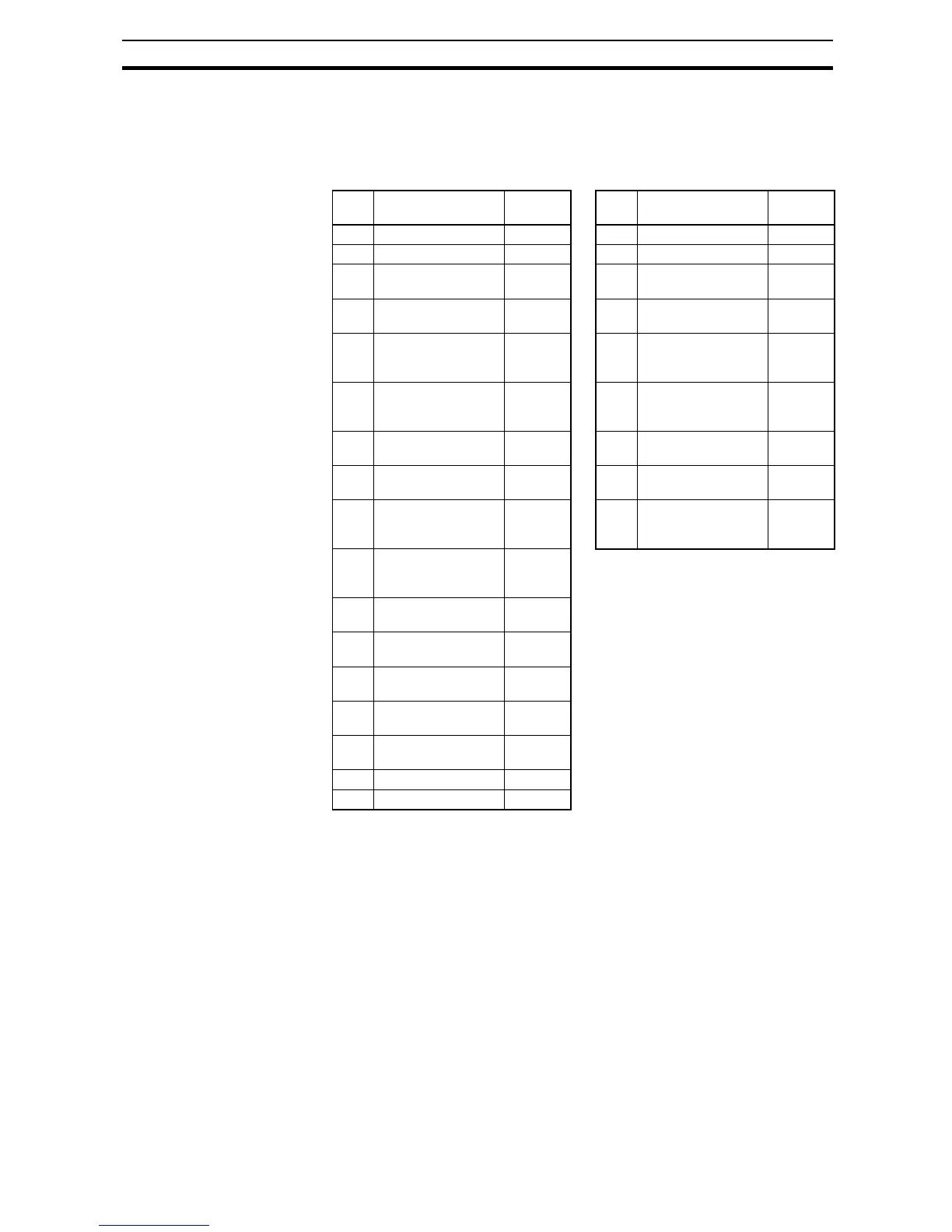
Write in Holding Registers [17h]:
This function is to read and write data in consecutive holding registers. An
example follows:
• Write "50.0 Hz" as the set frequency (F001) in an inverter having a slave
address "1" and then to read out the output frequency (d001).
Note 1 Register address value (transmitted on Modbus line) is 1 less than the Regis-
ter Number.
When writing in selected holding registers fails, see the exception response.
No. Field Name Example
(Hex)
No. Field Name Example
(Hex)
1 Slave address *1 01 1 Slave address 01
2 Function code 17 2 Function code 17
3 Start address to
read *3 (high order)
10 3 Byte number n 04
4 Start address to
read *3 (low order)
00 4 Register Data 1
(high order)
00
5 Number of holding
registers to read
(high order)
00 5 Register Data 1 (low
order)
00
6 Number of holding
registers to read
(low order)
02 6 Register Data 2
(high order)
13
7 Start address to
write *3 (high order)
00 7 Register Data 2 (low
order)
88
8 Start address to
write *3 (low order)
00 8 CRC-16 (high order) F4
9 Number of holding
registers to write
(high order)
00 9 CRC-16 (low order) 71
10 Number of holding
registers to write
(low order)
02
11 Byte number to
write*2
04
12 Change data 1
(high order)
00
13 Change data 1
(low order)
00
14 Change data 2
(high order)
13
15 Change data 2
(low order)
88
16 CRC-16 (high order) F4
17 CRC-16 (low order) 86
 Loading...


