195
Using Intelligent Input Terminals Section 4-5
4-5-25 Limit signal of homing, Trigger signal of zero-return
These functions are used for homing performance.
One of three types of homing operations can be selected by homing mode
selection (
P068). When a homing operation ends, the current position counter
is cleared (to 0). Use homing direction selection (
P069) to select the direction
of homing operation. If homing operation is not performed, position control is
performed based on the assumption that the motor position detected at
power-on is the origin.
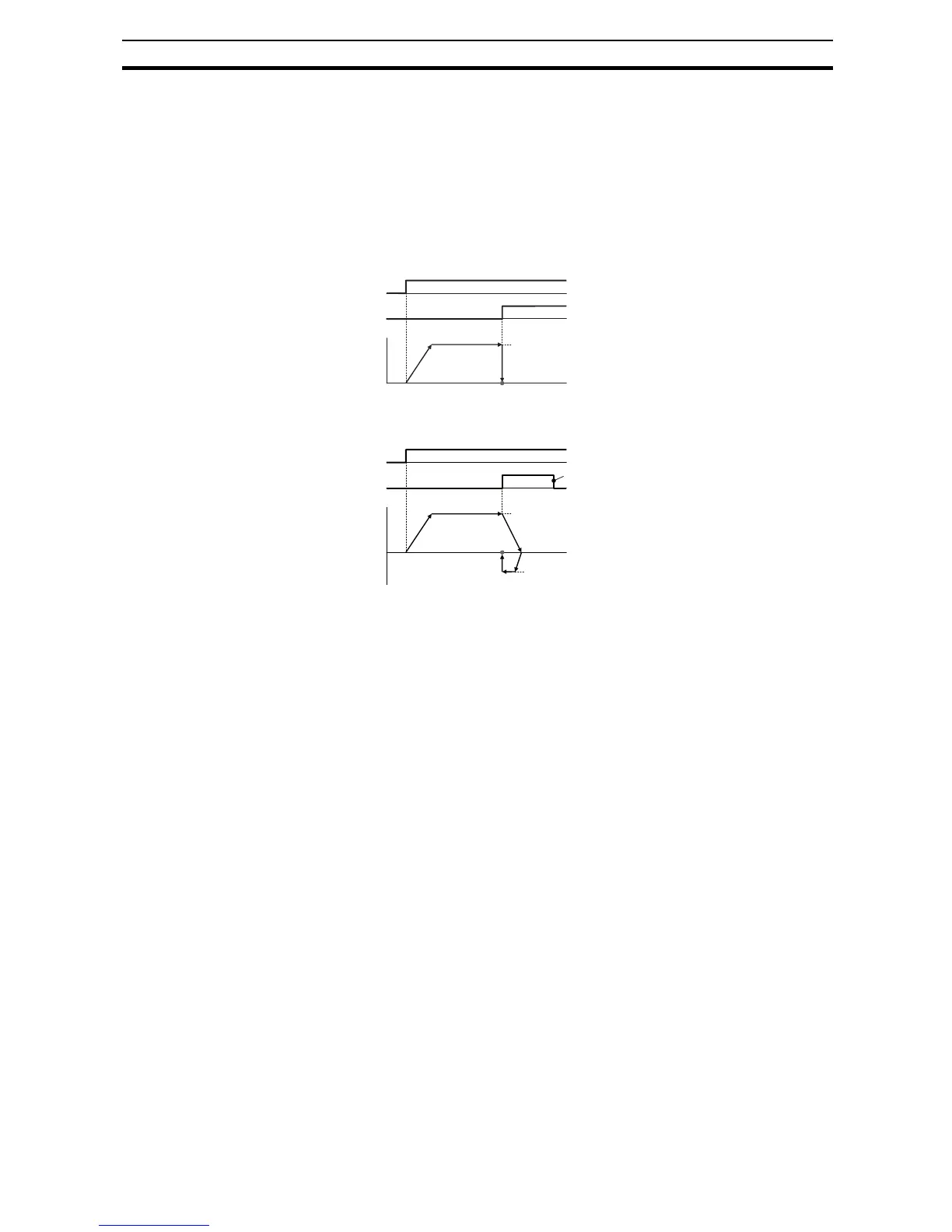
<1> Low speed homing (P068=00)
ORG
ORL
Output
freq.
ON
ON
Origin Position
(1)
(2)
(3)
Low speed homing
(P070)
1. The inverter accelerates the
motor for the specified ramp time
to the low speed homing.
2. It runs the motor at the low
speed homing.
3. It performs positioning when the
ORL signal is given.
<2> High speed homing (P068=01)
ORG
ORL
Output
freq.
ON
ON
Origin
Position
(1)
(2)
(3)
High speed homing
(P071)
(4)
Low speed homing
(P070)
(5)
(5)
1. The inverter accelerates the mo-
tor for the specified ramp time to
the high speed homing.
2. It runs the motor at the high
speed homing.
3. It starts deceleration when the
ORL signal is turned on.
4. It runs the motor in the reverse
direction at the low speed hom-
ing.
5. It performs positioning when the
ORL signal is turned off.
 Loading...


