16
Section 1 FEATURES
ZFV
User’s Manual
Section 1
Basic Configuration
Basic Configuration
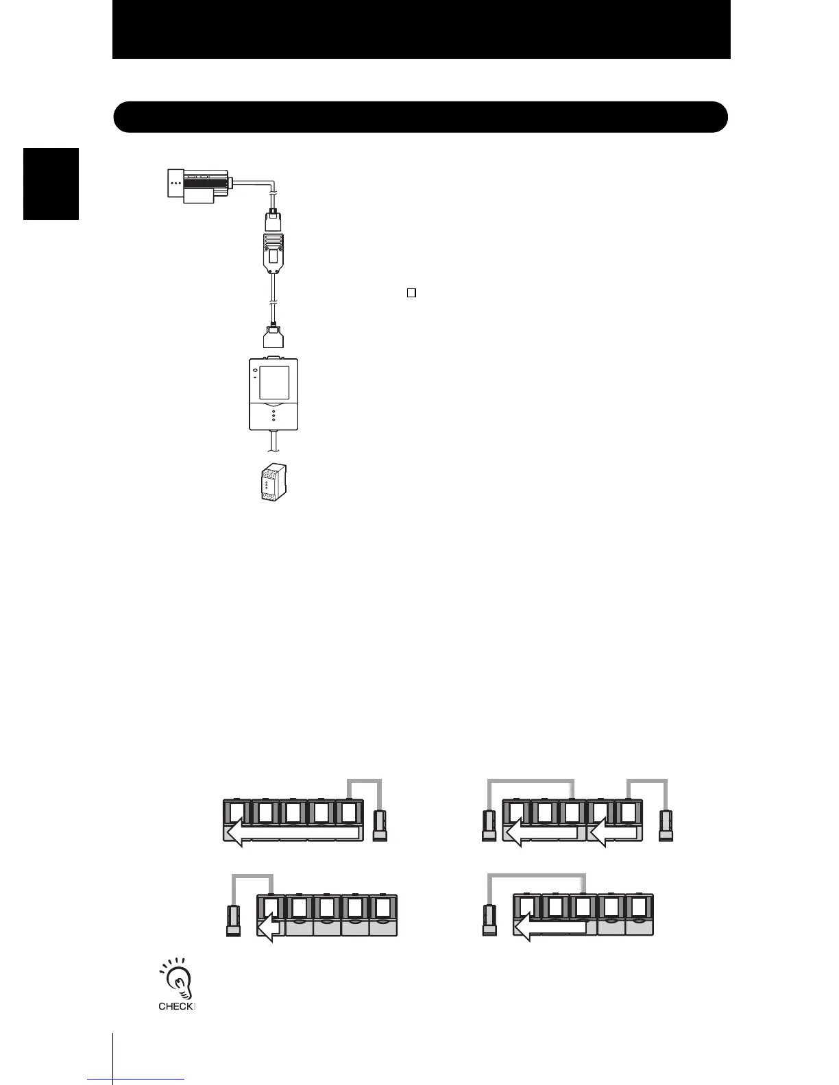
The figure below shows the Basic Configuration of the ZFV Series.
■ Application Expanded Configuration
Up to five Amplifier Units can be gang-mounted.
When the Amplifier Unit is gang-mounted, a wider range of applications can be sup-
ported as simultaneous processing of multiple areas and measurement items can be
combined.
The image captured by the Sensor Head is transferred to the leftmost Amplifier Unit, so
connect to the rightmost Amplifier Unit.
RUN
OUTPUT
Amplifier Unit
Detects workpieces as images.
• Narrow view type ZFV-SR10
• Wide view type ZFV-SR50
Used for confirming images and menus, performing measurement
processing, and outputting the result of processing.
• Single-function type ZFV-A10/-A15
• Standard type ZFV-A20/-A25
Recommended OMRON power supply
(1) When 1 Amplifier Unit is connected
S82K-01524 (DC24V, 0.6A)
(2) When 2 or 3 Amplifier Units are connected
S82K-05024 (DC24V, 2.1A)
(3) When 4 or 5 Amplifier Units are connected
Prepare the required number of (1) and (2)
power supplies above.
Power supply
DC24V (+10%, -15%)
Extension Cord
ZFV-XC3BV2(3m)/XC8BV2(8m)/XC3BRV2(3m)
Used between a Sensor Head and Amplifier Unit.
Two ZFV-XC B(R)V2 cords can be coupled together to
extend the cord length.
Sensor Head
Right
Wrong
Right
Wrong
• The maximum number of Amplifier Units that can be connected is five regardless of the number
of connected Sensor Heads.Six or more Amplifier Units cannot be connected.
• Provide power to all gang-mounted Amplifier Units.

 Loading...