Section 4
When Gang-mounting Amplifier Units
91
ZFV
User’s Manual
Section 4 APPENDIX
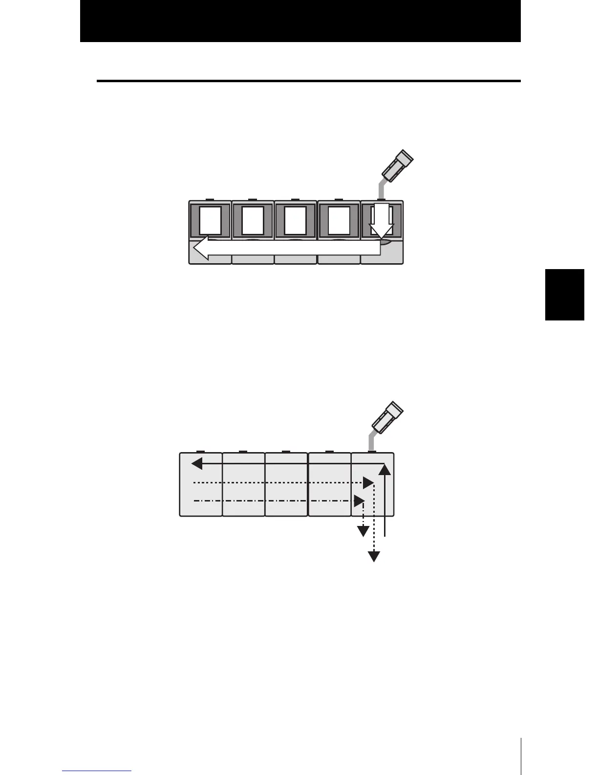
Data route
■ Measurement image
The measurement image flows from the right-side amplifier unit towards the left-side.
Image input timing delays do not occur.
■ I/O signal
The TRIG signal flows from the right-side amplifier unit towards the left-side. Input tim-
ing delays do not occur.
In contrast, ENABLE signals and OUTPUT signals combining all amplifying units can
be output from the furthest right amplifier unit as ENABLE signals and OUTPUT signals
flow from the left-side amplifier unit to the right-side.
TRIG signal
ENABLE signal
OUTPUT signal

 Loading...