70
Section 3 SETUP
ZFV
User’s Manual
Section 3
Settings During Application Extended Connection
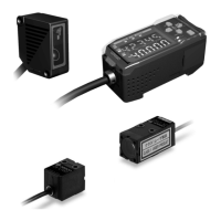
Setting the presence of Sensor Head
Set whether or not a Sensor Head is connected.
MENU Mode-[SYS2]-[LINKSET]-[HEAD]
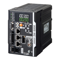
Setting output content
Set the output content of the measurement result.
This item is displayed only the Amplifier Unit whose [TRIG/TRIG] setting is set to [I/O].
MENU Mode-[SYS2]-[LINKSET]-[OUTPUT]
Output image p.93
Setting Description
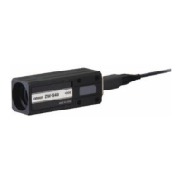
USE (default value) Select this for Amplifier Unit to which a Sensor Head is currently connected.
Measurement is performed using the input image from the currently connected
Sensor Head.
NOT USE Select this for Amplifier Unit to which a Sensor Head is currently not connected.
Measurement is performed from the image transferred from the Sensor Head
gang-mounted on the right side.
Setting Description
ALL The measurement results of all gang-mounted Amplifier Units are integrated, and
output as an overall judgment result.
EACH (default value) The measurement result of each Amplifier Unit is output from the respective Ampli-
fier Unit.

 Loading...