18
Section 1 FEATURES
ZFV
User’s Manual
Section 1
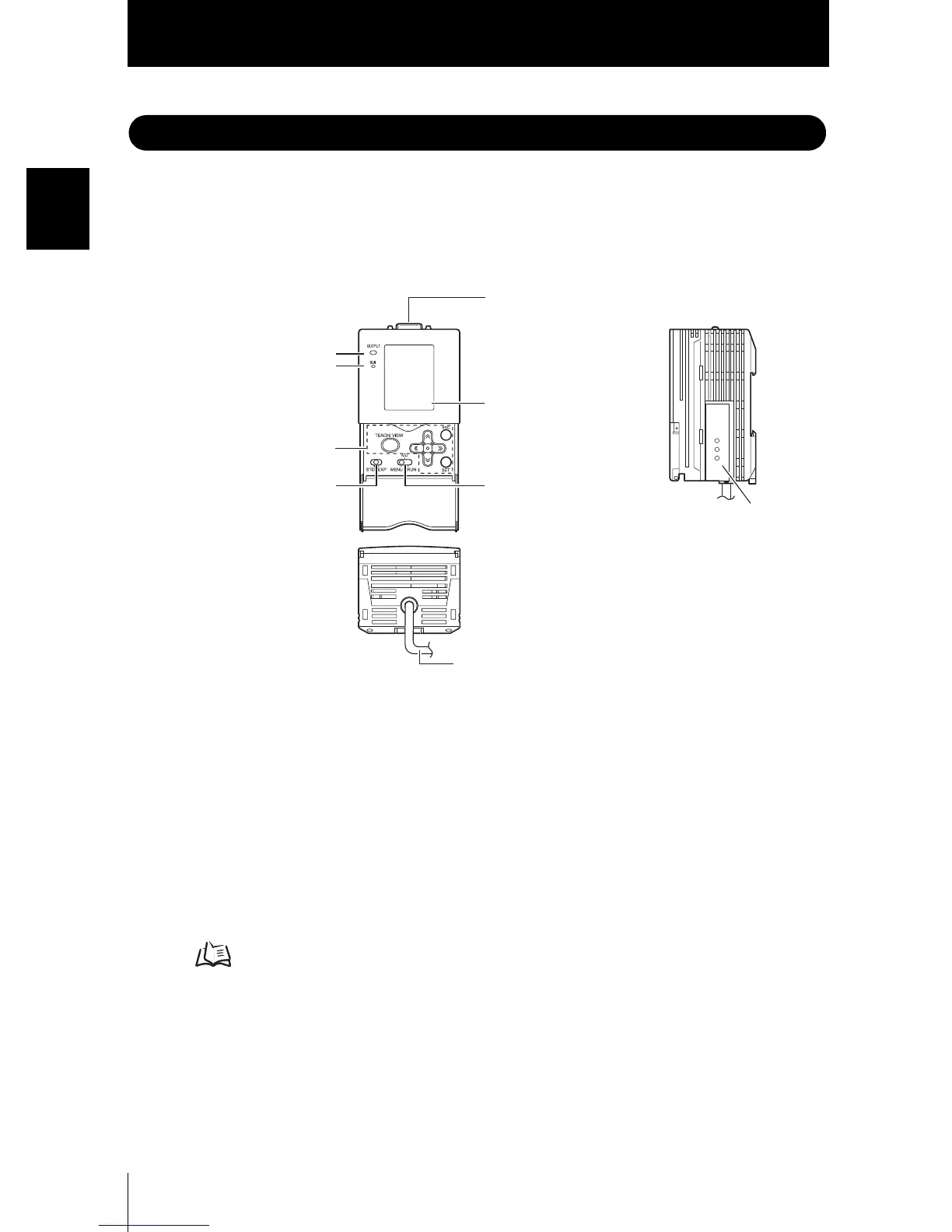
Part Names and Functions
Part Names and Functions
The following describes the names and functions of parts on the Amplifier Unit and Sensor
Head.
■ Amplifier Unit
(1) OUTPUT indicator
The Output indicator lits when the OUTPUT signal turns ON.
(2) RUN indicator
The RUN indicator turns ON in the RUN mode.
(3) Control keys
The Control Keys are for setting measurement conditions and other information.
Displays and Key Operations p.45
(4) Menu selector switch
This switch selects the setup menu.
STD...Standard menu. Select this when setting the minimum required items for
measurement.
EXP...Expert menu. Select this item when making a more detailed setup.
(1) OUTPUT indicator
(2) RUN indicator
(3) Control keys
(9) I/O cable
(4) Menu selector switch
(8) Coupler
(6) LCD monitor
(5) Mode selector switch
(7) Sensor Head connector

 Loading...