4.16
ELECTRONIC FUEL INJECTION
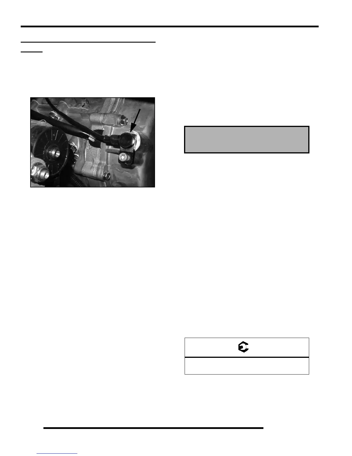
CRANKSHAFT POSITION SENSOR
(CPS)
Operation Overview
The engine speed sensor is essential to engine operation,
constantly monitoring the rotational speed (RPM) and position
of the crankshaft.
A ferromagnetic 60-tooth ring gear with two consecutive teeth
missing is mounted on the flywheel. The inductive speed sensor
is mounted 1.0 0.26 mm (0.059 0.010 in.) away from the
ring gear. During rotation, an AC pulse is created within the
sensor for each passing tooth. The ECU calculates engine speed
from the time interval between the consecutive pulses. The two-
tooth gap creates an “interrupt” input signal, corresponding to
specific crankshaft position for PTO cylinder. This signal serves
as a reference for the control of ignition timing by the ECU.
Synchronization of the CPS and crankshaft position takes place
during the first two revolutions each time the engine is started.
This sensor must be properly connected at all times. If the sensor
fails or becomes disconnected for any reason, the engine will
quit running.
CPS Test
The crankshaft position sensor is a sealed, non-serviceable
assembly. If fault code diagnosis indicates a problem within this
area, test and correct as follows:
1. Disconnect main harness connector from ECU.
2. Connect an ohmmeter between the pin terminals. A
resistance value of 560 10% at room temperature (20
C, 68 F) should be obtained. If resistance is correct, check
the mounting, air gap, toothed ring gear (damage, runout,
etc.), and flywheel key.
3. Disconnect speed sensor connector from wiring harness.
(the connector with one heavy black lead) Viewing the
connector with dual aligning rails on top, test resistance
between the terminals. A reading of 560 10% should
again be obtained.
NOTE: If the resistance is incorrect, remove the
screw securing the sensor to the mounting bracket
and replace the sensor. If the resistance in step 2
was incorrect, but the resistance of the sensor alone
was correct, test the main harness circuit between
the sensor connector terminals and the
corresponding pin terminals in the main connector.
Correct any observed problem, reconnect the
sensor, and perform step 2 again.
CPS Replacement
1. Disconnect sensor harness connector.
2. Using a 6 mm hex wrench, remove the retaining bolt and
replace the sensor, using a light coating of oil on the o-ring
to aid installation.
3. Torque the retaining bolt to specification.
Crankshaft Position Sensor:
560
10% (20 C, 68 F)
= T
CPS Retaining Bolt Torque:
25 in. lbs. (2.8 Nm)

 Loading...


