7.11
FINAL DRIVE
7
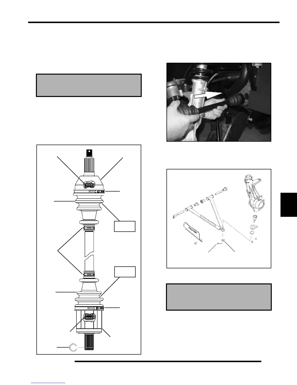
20. Pull out on the drive shaft to center the joint in the housing.
Slide a straight O-ring pick or a small slotted screw driver
between the large end of the boot and the joint housing and
lift up to equalize the air pressure in the boot.
21. Position the boot lip in its groove. Install and secure the
boot with the large clamp using the “earless” clamp pliers.
Exploded View
NOTE: Refer the “Electronic Parts Catalog” for
required parts to service the drive shaft. Some drive
shafts have “Boot Replacement Kits” that include a
new boot, clamps, and the required amount of
grease.
Installation
1. Install new spring ring on drive shaft. Apply an anti-seize
compound to splines. Align splines of drive shaft with
front gearcase and install by lightly tapping on drive shaft
with rubber faced hammer.
2. Install drive shaft in strut.
3. Install the lower A-arm onto the lower ball joint, torque nut
to 25 ft. lbs. (35 Nm) and install new cotter pin.
4. Install hub and tighten spindle nut to 70 ft. lbs. (95 Nm).
CV Boot Clamp Pliers
Earless Type: 8700226
Circlip
CV Joint
Boot
Large
Small
Clamp
Clamps
Boot
Large
Clamp
Plunging
Joint
Circlip
Circlip
Grease
Grease
Front Spindle Nut Torque
70 ft. lbs. (95 Nm)
25 ft. lbs.
(35 Nm)
Cotter Pin

 Loading...


