5.8
BODY / STEERING / SUSPENSION
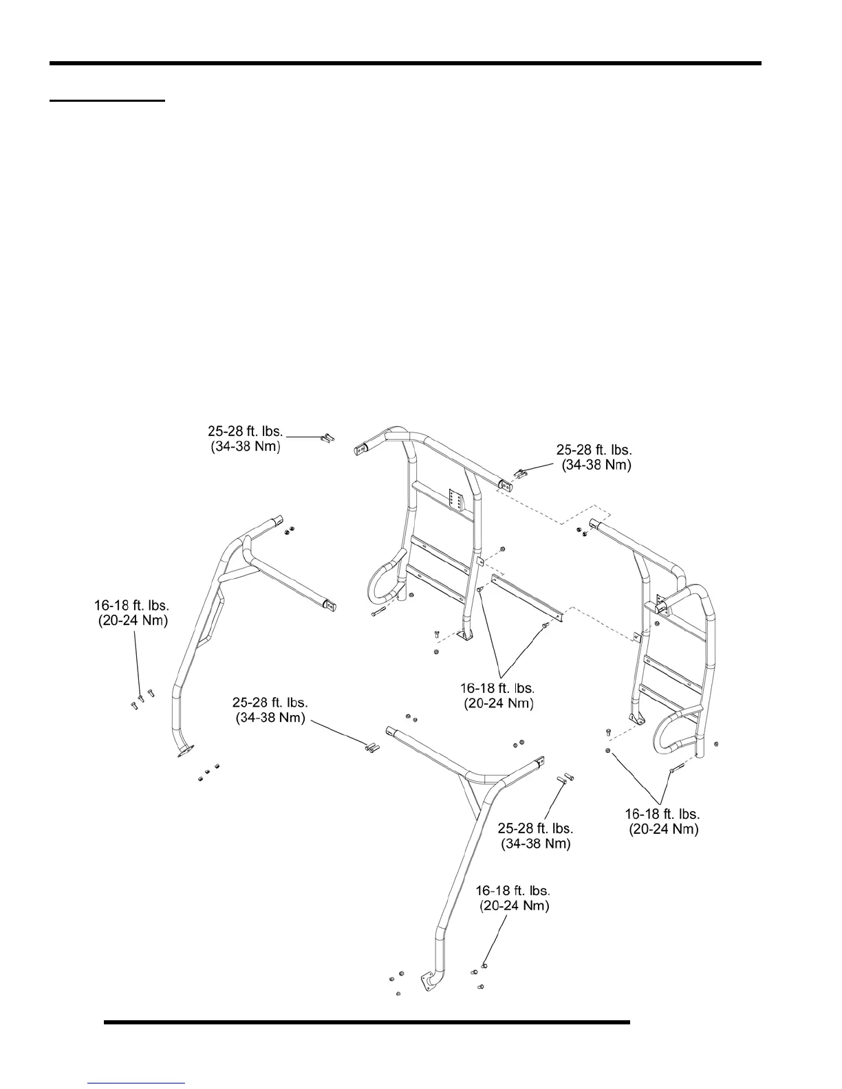
CAB FRAME
Assembly / Removal (6x6)
1. Assemble the two rear cab frames at the coupler joint and secure with two 3/8" screws and nuts. Assemble the front frame in
same manner. Leave all fasteners finger tight.
2. Assemble the center cross bracket to the rear cab frame and secure with two 5/16”-18 x .75” hex bolts and nuts. Tighten 5/16"
bolts to 16-18 ft. lbs. (20-24 Nm).
3. Assemble the front cab frame to the rear cab frame at both side coupler joints and secure with 3/8" screws and nuts. Leave all
fasteners finger tight.
4. Place the assembled cab frame onto the vehicle and align the rear mount holes. Secure the rear of the frame using the two 5/
16”-18 x 2.25” bolts and nuts on the outer tubes, and the two 5/16”-18 x .75” bolts and nuts on the inner mounts. Tighten all
5/16" bolts to 16-18 ft. lbs. (20-24 Nm). NOTE: Tighten all nuts finger tight, then tighten to specification.
5. Secure the front cab frame flanges to the vehicle with 5/16”-18 x .75” bolts and nuts. Tighten all 5/16" bolts to 16-18 ft. lbs.
(20-24 Nm). NOTE: Tighten all nuts finger tight, then tighten to specification.
6. Tighten all 3/8" cab frame screws to 25-28 ft. lbs. (34-38 Nm).
7. Check all nuts and bolts for proper torque and installation. To remove the cab frame, reverse the installation instructions.

 Loading...


