7.23
FINAL DRIVE
7
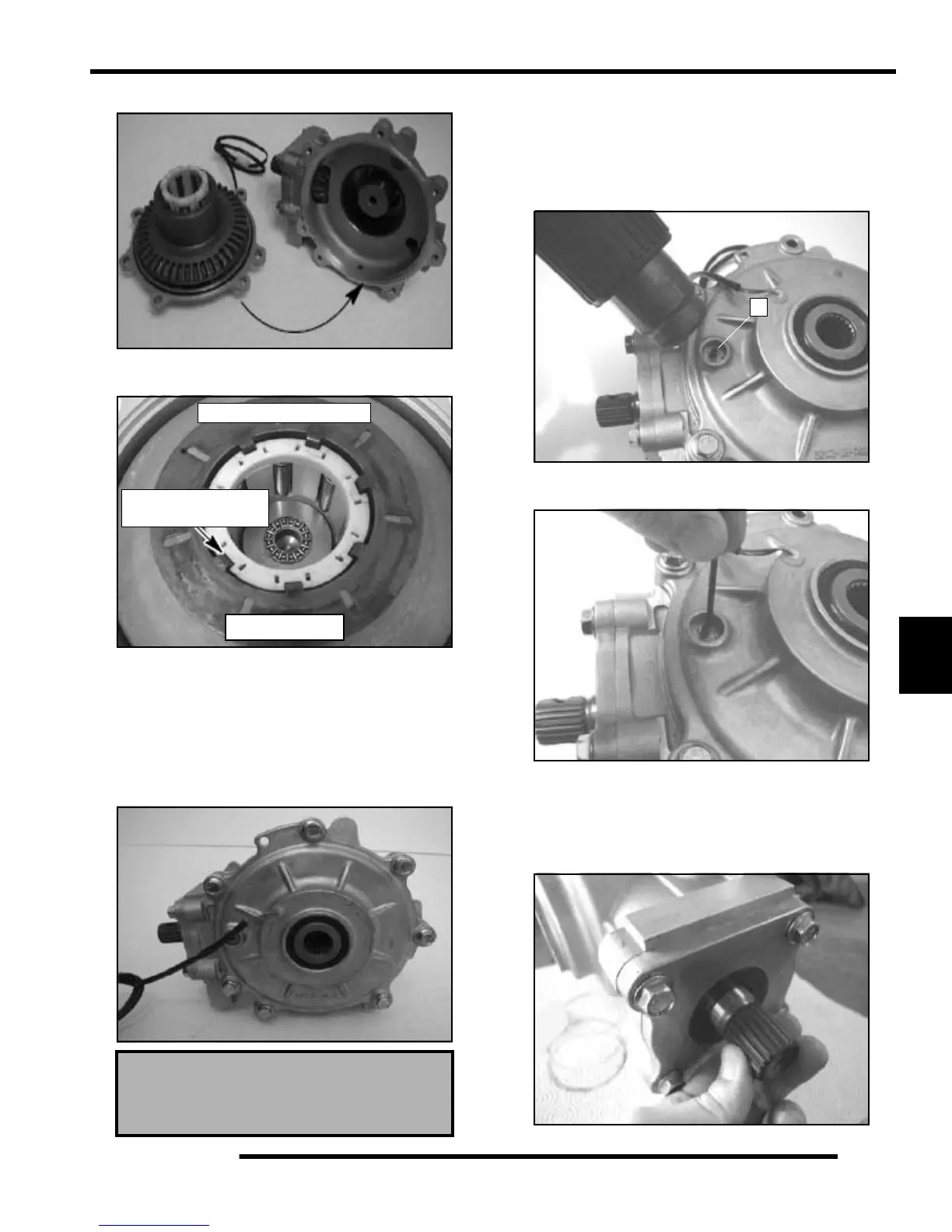
11. Install the output cover assembly onto the main gearcase.
NOTE: Be sure armature plate tabs are placed into
the slots on roll cage. (See Reference Photo)
NOTE: This photo is for reference only, the armature
plate is actually installed in the output cover.
12. Install output cover with new O-ring and torque bolts to 17
ft. lbs. (23 Nm).
NOTE: Be sure the square O-ring is placed flat on
the cover surface. If the O-ring is twisted fluid
leakage may occur.
Backlash Pad (Thrust Pad) Adjustment
1. Lay the gearcase on the side with the output cover facing
up.
2. The backlash screw has Loctite applied to it. Use a heat gun
to lightly heat up the Loctite on the screw (A).
3. Using a hex wrench, turn the back-lash screw out 3-4 turns.
Re-apply red Loctite onto the bottom screw threads.
4. Turn the screw in until it is lightly seated, then turn the
screw out 1/4 turn.
5. Set the gearcase upright. Rotate the pinion shaft at least 4
times. This ensures the ring gear completes one full
rotation.
Cover Bolts Torque:
17 ft. lbs. (23 Nm)
Armature plate design may
differ from what is shown
Photo for reference only
Armature plate tabs
fit into roll cage slots
A

 Loading...


