10.30
ELECTRICAL
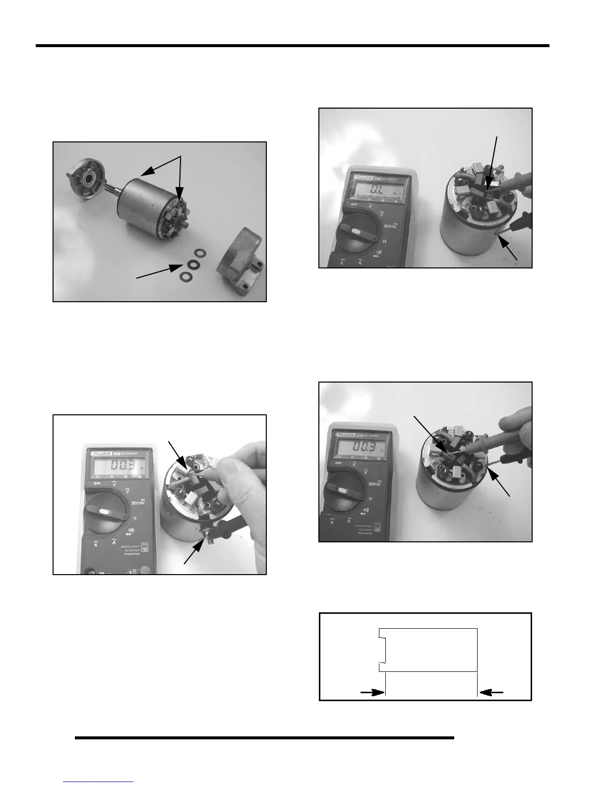
NOTE: Note the alignment marks on both ends of
the starter motor casing. These marks must align
during reassembly.
3. Remove the front bracket assembly and the rear bracket
assembly. Remove the shims from the armature shaft and
inspect the O-rings located on the armature housing.
NOTE: The shims will be replaced during
reassembly.
Brush Inspection / Replacement
1. Measure resistance between starter input terminal and
insulated brushes. The reading should be .3 ohms or less.
Remember to subtract meter lead resistance.
2. Measure resistance between insulated brush and starter
housing. Reading should be infinite (OL). Inspect
insulation on brush wires for damage and repair or replace
as necessary.
3. Slide positive brush springs to the side, pull brushes out of
their guides and remove brush plate. Slide brush end frame
off end of starter.
NOTE: The electrical input post must stay with the
field coil housing.
4. Measure resistance between ground brush and brush plate.
Resistance should be .3 ohms or less.
Brush Inspection
1. Measure length of each carbon brush. Replace brush
assembly when worn to 5/16” (8 mm) or less. The brushes
must slide freely in their holders.
O-Rings
Shims
Limit 5/16” (8 mm)
Brush Length

 Loading...


