5.19
BODY / STEERING / SUSPENSION
5
REAR A-ARM (4X4 CREW)
Replacement
NOTE: Use the exploded view on the next page as
reference during the procedure.
1. Elevate and safely support vehicle with weight removed
from the rear wheel(s).
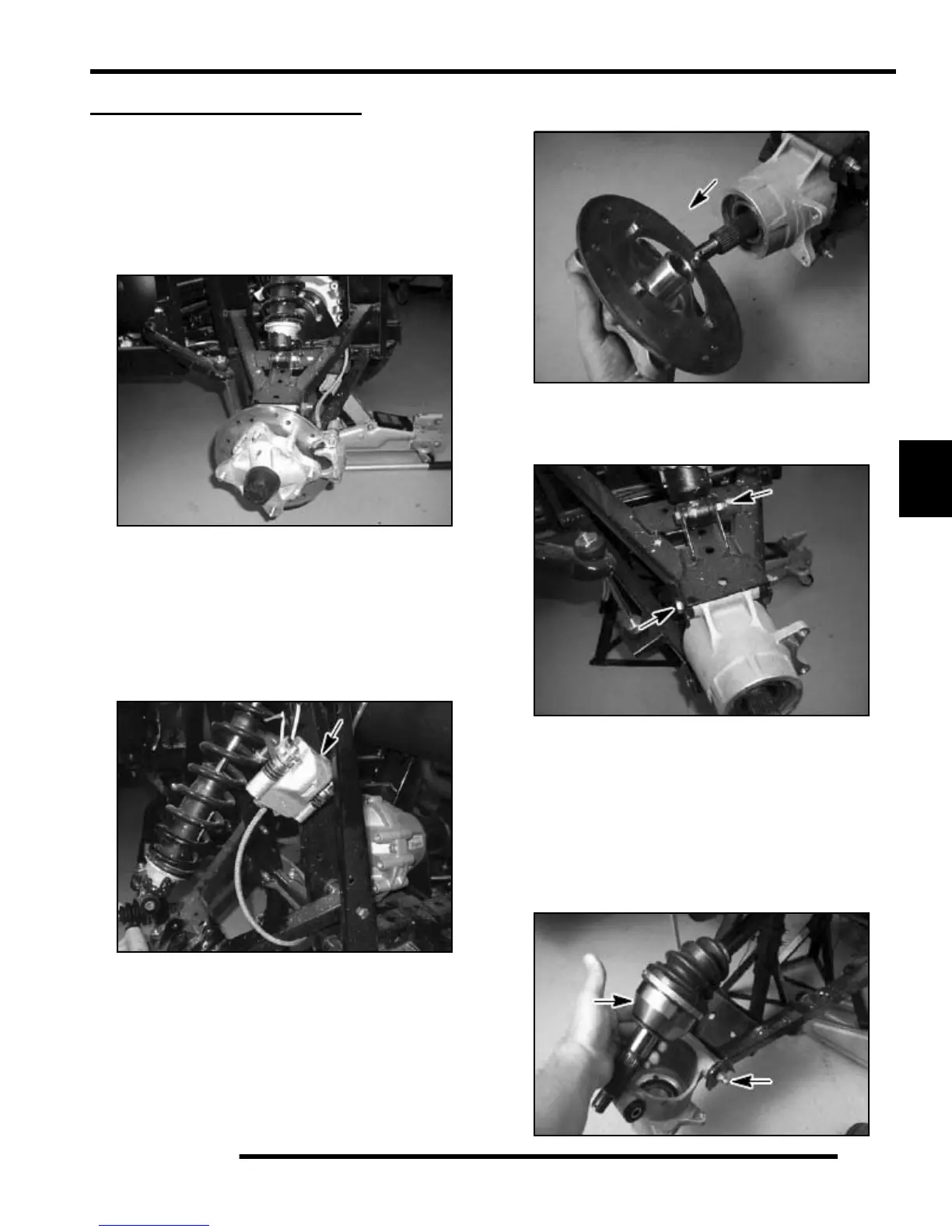
2. Remove the wheel nuts, washers, and wheel.
NOTE: To ease the removal of the spindle bolt,
remove the hub cap and loosen the spindle bolts
before removing the wheel.
3. Remove the hub cap, cotter pin, spindle bolt, and washer.
4. Remove the brake caliper. Suspend the brake caliper from
the frame with a wire.
NOTE: Do not let the brake caliper hang from the
brake line or damage may occur.
5. Remove the hub and brake disc assembly by sliding it off
of the axle.
6. Remove the bolt that secures the shock and coil to the upper
A-arm.
7. Remove the bolt that secures the wheel carrier to the upper
A-arm.
8. Loosen two bolts that secure the A-arm to frame by
alternating each about 1/3 of the way until A-arm can be
removed. Perform this procedure on the upper A-arm. See
exploded view, next page.
9. Examine the A-arm bushing and A-arm shaft. Replace if
worn. Discard hardware.
10. To remove the lower control arm, the wheel bearing carrier
needs to be removed. Remove the upper and lower wheel
carrier bolts and slide the rear drive shaft from the carrier.
(See Chapter 7 for more details).
Shock Bolt
Wheel Carrier
Bolt

 Loading...


