7.20
FINAL DRIVE
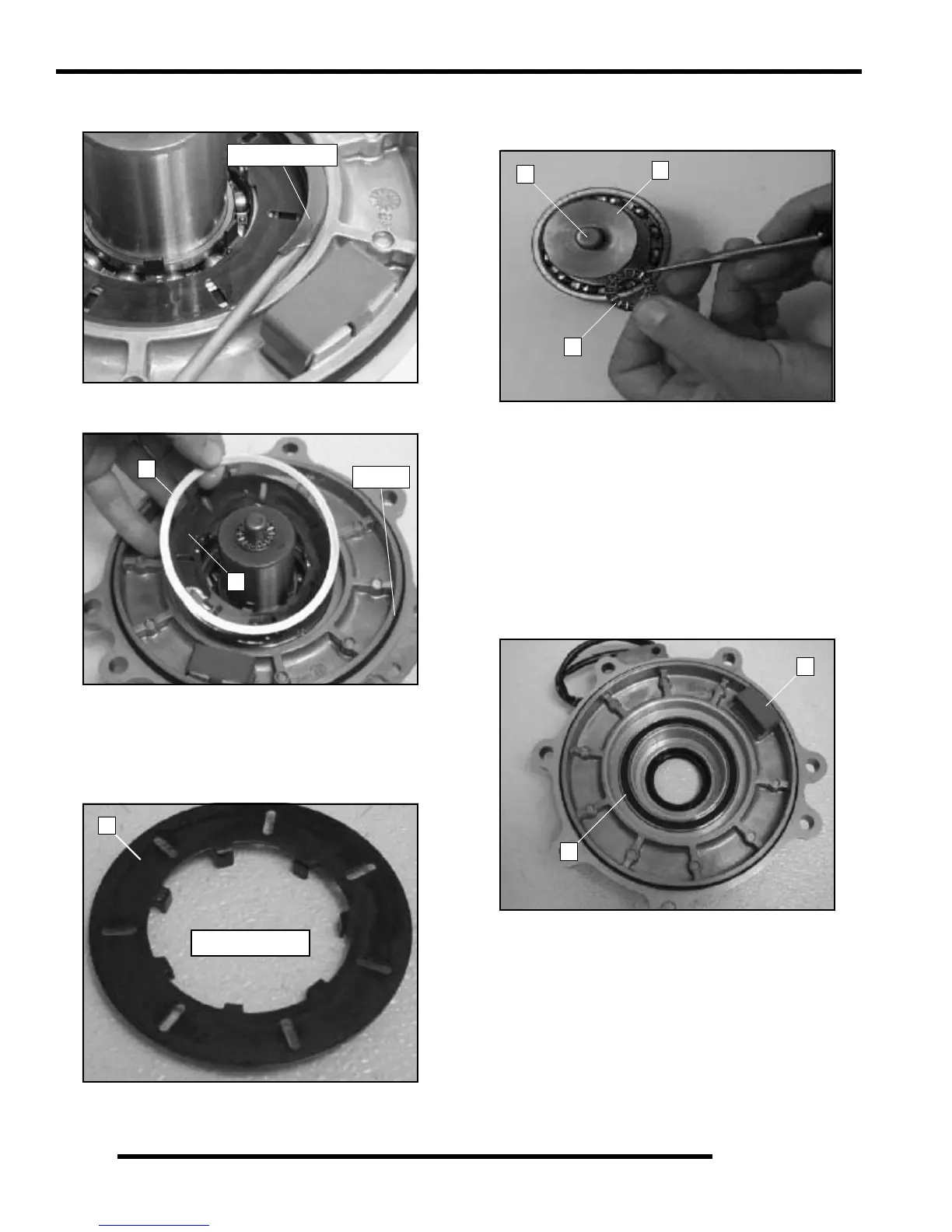
10. Use a flat head screwdriver to remove the retaining ring
from the output cover.
11. Remove the spacer washer (D), armature plate (E), and
rubber O-ring from the output cover.
12. Inspect the armature plate (E) for a consistent wear pattern.
Uneven wear of the armature plate (E) indicates a warped
plate, which may cause intermittent operation.
NOTE: See "FRONT GEARCASE DIAGNOSIS"
earlier in this chapter for more details.
13. Remove the output hub (G) from the cover. remove the
thrust bearing (F) from the output hub (G). Inspect the
thrust bearing (F) and the dowel (H).
14. Inspect the magnetic coil (I) in the output housing.
NOTE: See "FRONT GEARCASE DIAGNOSIS"
earlier in this chapter for more details on the coil.
15. Inspect the back lash pad (J) for excessive wear.
NOTE: The backlash for the centralized hilliard is set
at the factory. No adjustment is required, unless the
front cover needs to be replaced, or the back lash
pad screw is removed. See the "Backlash Pad
Adjustment” procedure later in this chapter for
details on backlash setting.
Retaining Ring
D
E
O-Ring
E
Armature plate design may
differ from what is shown
H
G
F
I
J

 Loading...


