Do you have a question about the Ricoh OR-C1 and is the answer not in the manual?
Covers general safety guidelines, hazard warnings, and precautions to prevent injury and ensure safe operation.
Details precautions for laser units, emphasizing eye protection and proper handling to prevent hazardous radiation exposure.
Outlines essential safety measures for operating and handling the machine, including movement and electrical safety.
Explains symbols used in the manual and lists registered trademarks for product identification.
Defines the meaning of Warning, Caution, and Note symbols used throughout the manual for hazard communication.
Provides general information on specifications, supported paper sizes, software accessories, and optional equipment.
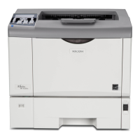
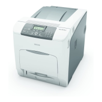
Details the system configuration and options, illustrating machine components and their interconnections.
Highlights differences between new and predecessor models to assist users with prior experience.
Specifies environmental conditions, machine leveling, space clearance, and power requirements for proper installation.
Details input voltage levels, permissible fluctuations, and electrical safety precautions for connecting the machine.
Covers connecting peripherals, accessory checks, and the step-by-step installation procedure for the copier unit.
Provides instructions on how to safely move the machine, including securing the scanner carriage.
Details the accessory check and installation procedure for the PB3120 paper feed unit.
Outlines the component check and installation procedure for the Caster Table Type D.
Details the accessory check and installation procedure for the PB3130 paper feed unit.
Details the accessory check and installation procedure for the LCIT PB3140.
Covers component check and installation procedure for the ARDF DF3060, including mounting and connecting cables.
Details component check and installation procedure for the 1 Bin Tray BN3090.
Outlines component check and installation procedure for the Internal Shift Tray SH3050.
Details component list and installation procedure for the Bridge Unit BU3050.
Covers accessory check and installation procedure for the SR3090 finisher, including necessary prior installations.
Details accessory check and installation procedure for the Booklet Finisher SR3100, including required optional unit installations.
Lists components and provides installation steps for the Punch Kit PU3000.
Details accessory check and installation procedure for the SR3070 finisher, including required prior installations.
Explains how to install the internal finisher, including component check and preparation steps.
Details the installation procedure for the punch kit for the internal finisher.
Provides instructions for installing the platen cover, including removal and alignment steps.
Outlines preparation and installation steps for the key counter bracket, including cutting off a part of the cover.
Details the installation procedure for the optional counter interface board, including connecting harnesses.
Explains the installation of anti-condensation heaters for the scanner unit and tray heaters for the copier and optional units.
Provides information on preventive maintenance intervals and procedures for various machine parts.
Covers essential pre-installation procedures, including printing jobs, disconnecting cables, and static discharge.
Lists and describes special tools and lubricants required for machine maintenance and component replacement.
Provides important safety and handling precautions for specific components like PCU, transfer roller, scanner unit, and fusing unit.
Details the procedure for removing and replacing various exterior covers of the machine, including front door, controller cover, and left cover.
Covers replacement procedures for scanner components, including exposure glass, original length sensors, scanner lamp, and scanner motor.
Details the procedure for replacing the scanner lamp, including chromaticity rank adjustment.
Explains the procedure for replacing the scanner motor assembly and the scanner motor itself.
Details the removal and replacement procedure for the lens block unit.
Covers the procedure for removing and replacing the SIO Board, including associated components.
Details the removal and reinstallation procedure for the front scanner wire, including component removal and wire routing.
Details the reinstallation procedure for the rear scanner wire, including component routing and tensioning.
Explains how to recalibrate the touch panel by adjusting specific marks on the screen for accurate input.
Covers critical safety warnings and procedures for replacing laser unit components, emphasizing eye protection.
Details the procedure for replacing the polygon mirror motor, including heat sink removal and mirror surface handling.
Explains the procedure for replacing the LD unit, including notes on variable resistors and screw tightness.
Details the procedure for removing and replacing the laser synchronization detector.
Provides detailed instructions for PCU removal and replacement, including cautions about drum surface handling and toner leakage.
Explains how to remove the pick-off pawls from the PCU.
Details the procedure for removing the PCU, which includes the OPC drum.
Covers the removal and replacement of charge and cleaning rollers, including re-installation notes for the charge roller.
Details the procedure for replacing the cleaning blade, including re-installation notes and toner application.
Explains how to prepare and handle the developer kit for installation.
Describes how to mix developer and check Vt, with notes on handling potential issues like dirty backgrounds.
Covers replacement of the transfer roller unit and image density sensor, including notes on surface care and sensor initialization.
Covers safety precautions and procedures for replacing the fusing unit and thermistors.
Covers safety precautions and procedures for removing paper feed unit components like paper guide plates and harness covers.
Details the removal of paper feed unit components, including gears and connectors.
Explains the replacement of separation, feed, and pick-up rollers, with notes on paper handling.
Details the replacement of paper lift motors and related components.
Covers the removal and replacement of the registration clutch.
Details the removal of brackets and covers to access and replace the transport clutches.
Explains the replacement of upper and lower feed clutches.
Details the removal and replacement of paper size sensors and their covers.
Covers the removal of the duplex unit to access and replace the registration sensor and its bracket.
Details the replacement of various sensors, including paper overflow, paper end, vertical transport, and paper feed sensors.
Explains how to remove, clean, and reassemble the dust collection box.
Covers the removal and disconnection of duplex unit components, including connectors, ground cables, and covers.
Details the removal of the duplex unit and guide plates for replacing the duplex entrance sensor.
Explains the removal of the duplex exit sensor assembly and replacement of the sensor.
Covers the removal and replacement of duplex entrance and by-pass motors, including bracket and harness connections.
Covers procedures for replacing controller board, NVRAM, and BCU board, including static discharge precautions.
Details the replacement procedure for the controller board, including component removal and static discharge precautions.
Explains the importance of backing up NVRAM data and lists data not saved to SD card during upload.
Covers adjustments for printing-related settings, including paper installation checks and test pattern usage.
Details how to adjust leading edge and side-to-side registration for various paper feed stations using SP modes.
Explains how to adjust leading/left side edge blank margins if registration cannot be adjusted within specifications.
Covers scanner adjustments for printing registration, side-to-side adjustment, and blank margin adjustment.
Explains how to adjust leading edge and side-to-side registration for platen mode copies.
Describes how to adjust image magnification using an S5S test chart.
Covers ADF image adjustments for registration and magnification.
Provides a procedure to calibrate the touch screen if it's not functioning correctly or after replacement.
Explains how to enter and exit SP mode, types of SP modes, and the importance of data-in LED status.
References appendices for detailed information on system SP tables.
Highlights that Service Program Mode is for service representatives only and may affect product quality if misused.
Advises to ask a supervisor for details on entering SP mode.
Instructs to press 'Exit' on the LCD twice to return to the copy window.
Categorizes SP modes by function: engine, printer, scanner, and fax.
Details the process of updating machine firmware using an SD card, including prerequisites and steps.
Provides preparation steps and the procedure for updating firmware via an SD card, including handling precautions.
Explains the procedure to update the LCD Control Board firmware using an SD card.
Details the procedure for updating the App2Me provider if a new version is available.
Covers the procedure for updating the browser unit, including SD card insertion and software steps.
Explains how to perform software reset and reset system settings or copier settings to defaults.
Details procedures for uploading NVRAM content to an SD card and downloading SP data from an SD card to NVRAM.
Covers uploading and downloading address book information, including preparation and procedure steps.
Provides information on the normal and error states of LEDs and the function of DIP switches for controller and BCU.
Explains how to use the Save Debug Log feature to capture and retrieve error information for analysis.
Provides information on service call conditions and refers to appendices for details.
Details the self-diagnostic test that runs at power-on, checking CPU, memory, HDD, and other components for malfunctions.
Explains how to perform a more detailed diagnostic test manually to check components not covered by the power-on self-diagnosis.
Describes common image problems like skewed, trapezoid, and parallelogram images, with visual examples.
Guides on how to check images using a trimming area pattern to identify skewed, parallelogram, or trapezoid images.
Provides procedures for correcting skewed, parallelogram, and trapezoid images based on test pattern results.
Details paper jam display information and provides a comprehensive table of jam codes, descriptions, and LCD displays.
Lists common electrical components like sensors and switches, their CN, PCB, state, and related symptoms or causes.
Provides a table of fuses, their ratings, and symptoms when turning on the main switch, with a caution on fuse replacement.
Explains energy saver modes, power consumption, and timer settings for optimizing energy usage.
Recommends keeping default settings and explains the impact of changing settings on energy costs and environment.
Details how to use SP8941 to measure machine status and estimate energy consumption.
Explains the effectiveness of duplex and combine functions in reducing paper usage and energy consumption.
Provides formulas for calculating paper reduction ratio based on duplex and combine functions.