Rockwell Automation Publication 2080-UM002N-EN-E - November 2022 263
Appendix A Modbus Mapping for Micro800
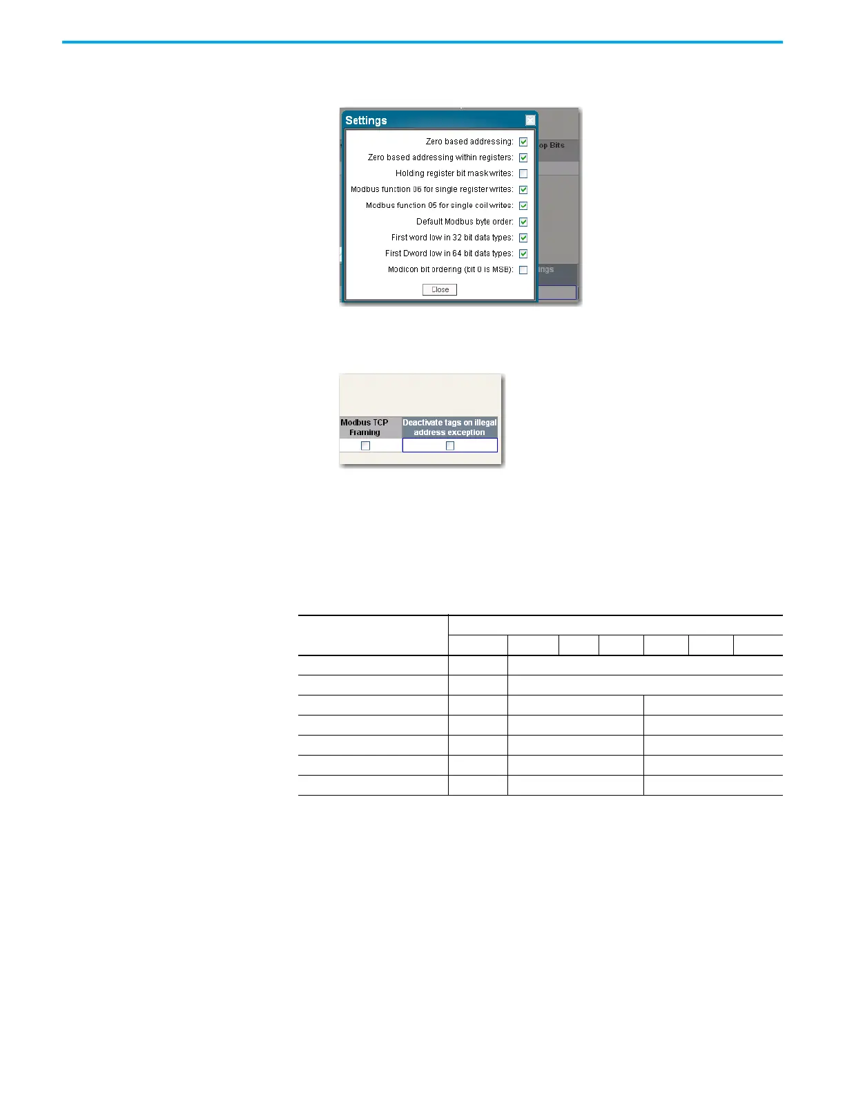
2. Set the Address of Micro800 slave to match the serial port configuration for the
controller.
3. Deactivate Tags on Error. This is to prevent the requirement of power cycling PV800
when new Modbus Mappings are downloaded from the Connected Components
Workbench software to the Micro800 controller.
Example 2, Micro800 (Master) to PowerFlex 4M Drive (Slave)
The following is the overview of the steps to be taken for configuring a PowerFlex 4M drive.
Parameter numbers listed in this section are for a PowerFlex 4M and will be different if you are
using another PowerFlex 4-Class drive.
• Connect the 1203-USB to the PowerFlex Drive and to the Computer.
• Launch the Connected Components Workbench software, Connect to the Drive and set
parameters.
To configure PowerFlex 4M, perform the following steps:
1. Double-click the PowerFlex 4M if it is not already open in the Connected Components
Workbench software.
2. Click Connect.
3. In the Connection Browser, expand the AB_DF1 DH+™ Driver.
Select the AB DSI (PF4 Port) and click OK.
Table 65 - Parameters
Parameter Name
Parameter Number
4M 4 40 40P 400 400N 400P
Start Source P106 P36
Speed Reference P108 P38
Comm Data Rate C302 A103 C103
Comm Node Addr C303 A104 C104
Comm Loss Action C304 A105 C105
Comm Loss Time C305 A106 C106
Comm Format C306 A107 C102
 Loading...