24 Rockwell Automation Publication 750-AT006D-EN-P - January 2022
Chapter 1 Background
FIR Filter Taps – More FIR taps filter out more noise, but reduces the overall bandwidth attainable in the velocity and position loops.
Similarly, a lower velocity feedback LPF bandwidth filters out more noise, but also reduces the overall bandwidth attainable in the velocity
and position loops. Typical values are given in Table 5
.
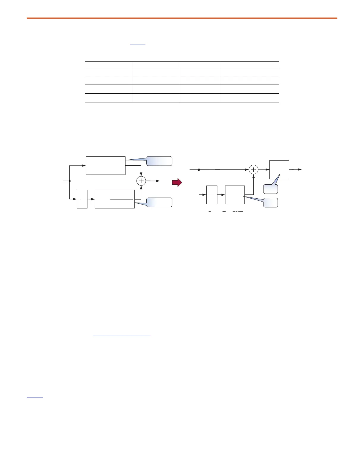
Velocity Regulator (V
REG
) – The velocity regulator consists of a proportional-integral (PI) controller. In legacy PowerFlex 755 drives, K
VP
is in
parallel with K
VI
. Here, legacy K
VP
10:645 [Speed Reg Kp] equals 10:636 [Speed Reg BW] in units of [rad/sec] times 10:76 [Total Inertia] in
units of [sec] and legacy K
PI
10:647 [Speed Reg Ki] has a squared relationship to K
VP
in units of [rad
2
/sec]. In this drive however, K
PP
is in
series with K
PI
and a factor of 2 is also applied to each gain.
Figure 22 - Velocity Regulator – from Parallel to Series Form
As a result, all tuning parameters represent bandwidths of physically measurable signals that are easy to understand. More importantly,
removing the squared relationships simplifies math when tuning a drive, because all gains and filter bandwidths are now related to each
other by simple ratios. This approach makes the tuning experience more transparent and intuitive.
Use the following equation to convert legacy velocity loop gains to PowerFlex 755T gains.
,
10:1952 [Servo Lock Gain] – This parameter sets the gain of an additional integrator in the velocity regulator. The effect of Servo Lock is to
increase stiffness of the velocity response to a load disturbance. It behaves like a position regulator with velocity feed forward, but without
the pulse accuracy of a true position regulator. The gain is normally set to less than one third of the system bandwidth, or for the desired
response. A value of zero disables this feature.
Load Observer – Load observer forces mechanical loads to behave consistently by compensating for unknown inertia, changing inertia, and
unknown amounts of friction, backlash, and non-rigidity present in the mechanics. This function allows out-of-box tuning to yield high
performance more often. See Load Observer
on page 29 for more information.
Acceleration Feed Forward (K
AFF
) – During velocity changes, a certain level of torque is required to overcome load inertia over and above
the level of torque used to run at constant speed. The acceleration feed forward signal attempts to predict the motor torque required to
accelerate and decelerate the load inertia. The 10:2070 [Accel FF Output] signal can be fed forward into the torque reference, becoming an
available input to the 10:34 [PsnVelTrq Actv] selector to be summed with 10:1969 [VReg Output] making for smoother accelerations and
decelerations, especially in high dynamic applications. These signals have acceleration units of [rev/sec
2
]. They are applied before the
Torque Scaler conversion to percent [% motor torque].
Table 6
lists the parameters for Acceleration Feed Forward.
Table 5 - Typical Velocity Feedback Filter Values
10:407 [Motor Poles] Encoder PPR Number of Taps Velocity Fb LPF BW [Hz]
81024*42…4 80
41024*41…3 160
8
1024
2
0 0 (Filter Off)
4
1024
2
0 0 (Filter Off)
TVP
JBWK *
VP
S
K2
VI
S
K2
s
1
2
4
*
z
KBW
K
VP
VI
s
1
K
VP
K
VP LegacyP645
2
J
T
LegacyP76
--------------------------------------------------------=
K
VI
K
VI LegacyP647
2
K
VP LegacyP645
----------------------------------------------------------------=
 Loading...


