8—The Home Screen
Roland VS-2480 Owner’s Manual www.rolandus.com 125
•
F3 (TR Mix)
—to show the playback levels of the tracks and the MONITOR and
MASTER bus levels.
•
F4 (AUXDIR)
—to show the master levels of the eight Aux send busses, eight Direct
busses and the MONITOR and MASTER bus levels.
•
F5 (OUTPUT)
—to show the levels of signals at the VS-2480 analog and digital output
jacks and connectors.
•
F6 (To Pre/To Pst)
—This switch allows you to select pre or post metering (Page 121)
when viewing the IN Mix, TR Mix and AUXDIR meter views. (The switch is grayed-
out when you’ve selected the INPUT or OUTPUT meter views.) When the pre/post
indicator (Page 120) shows “Pre,” you can press F6 (To Pst) to set the metering to
post-fader. When the indicator shows “Pst,” you can press F6 (To Pre) to switch to
pre-fader metering.
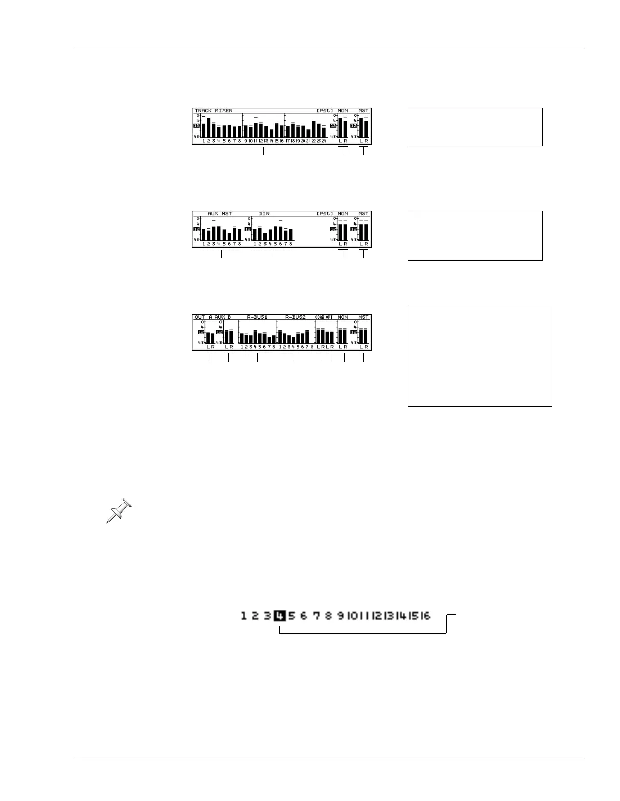
Input Peak Indicators
The input peak indicators help you set the level of signals coming into the VS-2480’s
analog input jacks. The 16 numbered indicators correspond to the 16 analog input jacks,
respectively.
When you’re adjusting a SENS knob (Page 32) to set the input level for a signal coming
into an analog input jack, a dark box appears around its input peak indicator if the
signal exceeds a pre-determined level—the INPUT PEAK LEVEL parameter (Page 362)
sets the input peak indicators to light when a signal reaches -6 dB, -3 dB or 0 dB. A light
gray line appears in the INPUT meters display view (Page 124) to show the input peak
indicators’ current volume threshold setting.
Pre- and post-fader AUXDIR metering shows Aux and direct bus signals before or after
the Aux bus and Direct bus master level controls—see Page 207 and Page 209.
1. Track Channels 1-24
2. Stereo MONITOR bus
3. Stereo MASTER bus
1. 2. 3.
1. Aux Busses 1-8
2. Direct Busses 1-8
3. Stereo MONITOR bus
4. Stereo MASTER bus
1. 3. 4.2.
1. Stereo Aux Output A
2. Stereo Aux Output B
3. R-BUS 1 Digital Outputs 1-8
4. R-BUS 2 Digital Outputs 1-8
5. Stereo digital coaxial outputs
6. Stereo digital optical outputs
7. Stereo MONITOR bus
8. Stereo MASTER bus
5. 8.
3. 4.1. 2. 6. 7.
In this illustration,
Input Channel 4’s
signal is too loud.
VS2480OMUS.book 125 ページ 2006年2月7日 火曜日 午後4時16分
 Loading...