Installing and Wiring the C7-613
2-8
C7-613 Control System
A5E00138934-03
2.4 Setting Up the Electrical Configuration and Connector
Pin Assignment
Pin Assignment of the C7-613 connectors
Tables 2-1 to 2-7 list the assignments of the C7-613 connections.
!
Caution
For functional reasons, the connector pin assignment is not compatible to the
predecessor products C7-621, C7-623, C7-626, C7-633 and C7-634.
Note
It is not possible to include the C7-613 in an ungrounded configuration
SF
FRCE
RUN
5 VDC
STOP
SIMATIC C7
Siemens
I/O
connector
X11 top
X12 bottom
Supply
connector
X1
Micro
Memory
Card
X7
Back-
plane bus
(I/O bus)
X5
Program-
ming
device
connec-
tion (MPI)
X2
I/O connector
X10 top
X13 bottom
Analog output X14
11
1
1
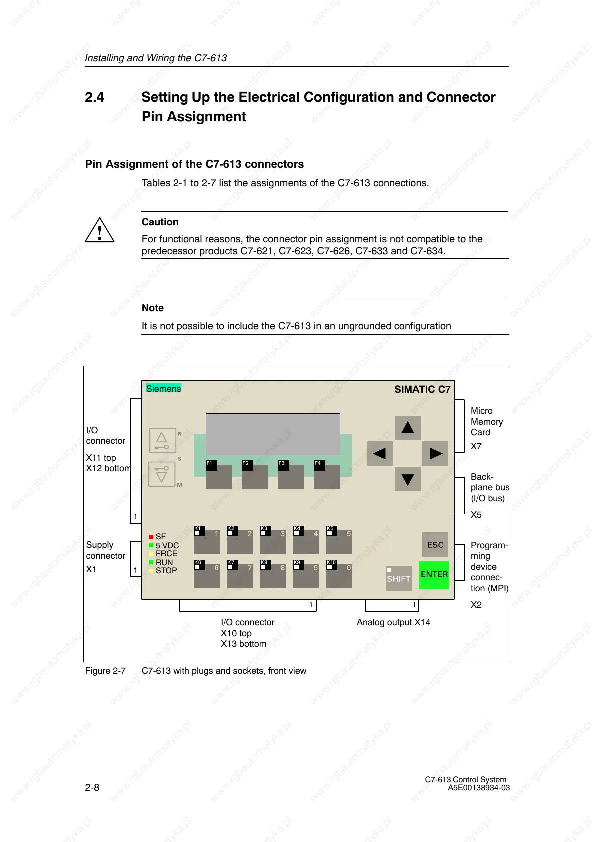
Figure 2-7 C7-613 with plugs and sockets, front view

 Loading...


