EasyManua.ls Logo

Siemens SIMATIC C7-613 User Manual

Siemens SIMATIC C7-613
200 pages
To Next Page IconTo Next Page
To Previous Page IconTo Previous Page
Page #76 background imageLoading...
Page #76 background image
Integration into the User Program
4-20
C7-613 Control System
A5E00138934-03
4.5 FB “HMI API” for the Basic HMI Functions
Function
The “HMI API” FB contains the essential functions for running the HMI functions.
The FB “HMI API” has to be called cyclically or time-controlled in your program.
Generation
In SIMATIC Manager, open the “C7 613” library and copy the “HMI API” FB to the
block container of your project.
Structure and Description
The parameters of the “HMI API” FB are classified as follows:
Parameters for specifying DB numbers: CFG_DB, EVENT_DB
Status parameters that provide information about the status of the FB:
RETVAL, ADDINFO
HMI parameters that are updated cyclically: LEDS, OBJ_TYPE, OBJ_NO,
KEYS
Job compartment: JOB_ID, JOB_PAR1 to 3
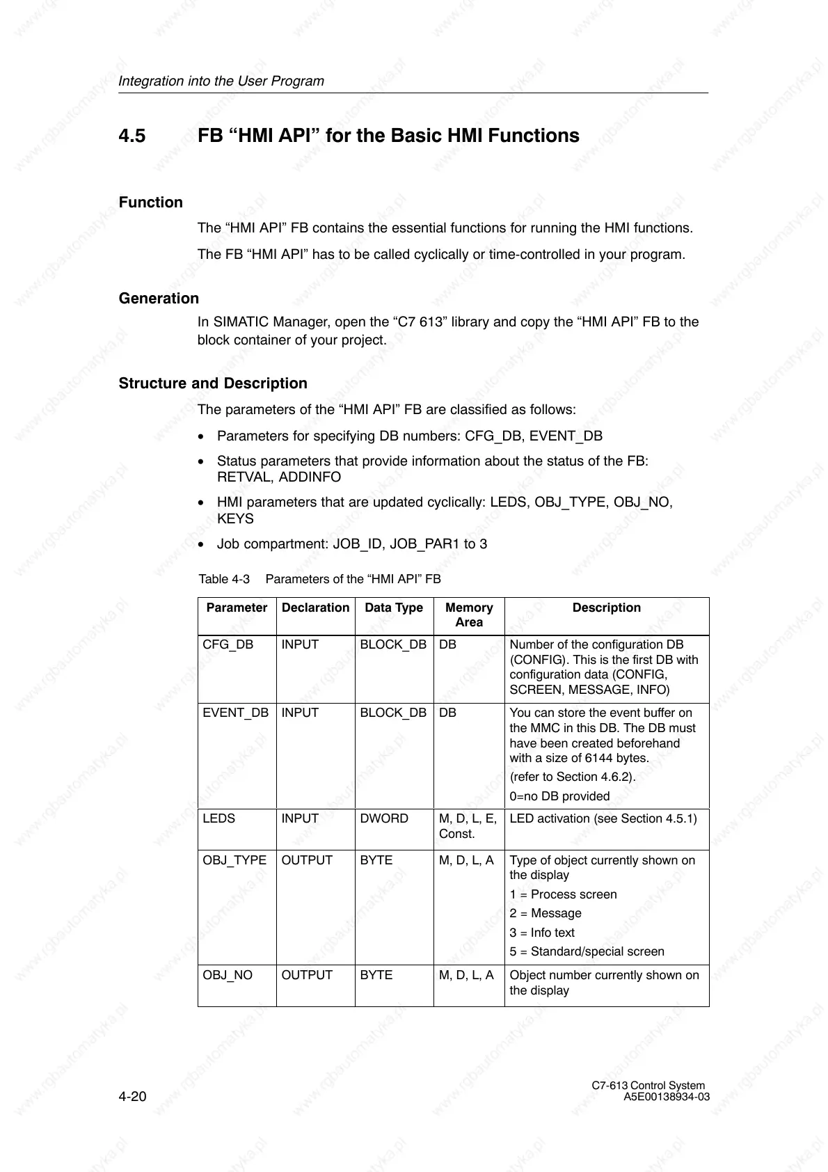
Table 4-3 Parameters of the “HMI API” FB
Parameter
Declaration Data Type Memory
Area
Description
CFG_DB INPUT BLOCK_DB DB Number of the configuration DB
(CONFIG). This is the first DB with
configuration data (CONFIG,
SCREEN, MESSAGE, INFO)
EVENT_DB INPUT BLOCK_DB DB You can store the event buffer on
the MMC in this DB. The DB must
have been created beforehand
with a size of 6144 bytes.
(refer to Section 4.6.2).
0=no DB provided
LEDS INPUT DWORD M, D, L, E,
Const.
LED activation (see Section 4.5.1)
OBJ_TYPE OUTPUT BYTE M, D, L, A Type of object currently shown on
the display
1 = Process screen
2 = Message
3 = Info text
5 = Standard/special screen
OBJ_NO OUTPUT BYTE M, D, L, A Object number currently shown on
the display

Table of Contents

Question and Answer IconNeed help?

Do you have a question about the Siemens SIMATIC C7-613 and is the answer not in the manual?

Siemens SIMATIC C7-613 Specifications

General IconGeneral
BrandSiemens
ModelSIMATIC C7-613
CategoryControl Systems
LanguageEnglish

Summary

Product overview

Design and Structure

Details the physical components and core architecture of the C7-613.

Product Scope and Accessories

Lists the components included in the C7-613 delivery and necessary accessories for operation.

Installing and Wiring the C7-613

Mechanical installation

Provides detailed steps and precautions for physically mounting the C7-613 unit.

Electrical Configuration and Pin Assignment

Details electrical connections and pin assignments for all C7-613 connectors.

Special Features of the C7-613

Operating Mode Selection

Explains how to select and change the operating modes (RUN, STOP, MRES) of the C7-613.

Integration into the User Program

Program Structure

Outlines the structure of programs for integrating HMI functions using FBs and DBs.

Creating Configuration Data

Details the process of creating configuration data for screens, messages, and info texts.

Operating the C7-613

Keyboard

Describes the layout and functions of the C7-613 keyboard, including system and function keys.

Entering Values

Details methods for entering numerical values using function keys or cursor keys.

Messages

Explains how messages (operational, fault, system) are displayed and managed on the C7-613.

Maintenance

Replacing the C7-613

Details the procedure and precautions for replacing a defective C7-613 unit.

Technical data

Technical Specifications for Control System

Lists detailed technical specifications for the C7-613 control system hardware.

Technical Specifications for CPU

Provides detailed technical specifications for the CPU module used in the C7-613.

Technical Specifications for Integrated I/O

Details the technical specifications for the C7-613's integrated digital and analog input/output modules.

Error Information for HMI FBs and System Messages

Error Information for HMI FBs

Provides information on error codes for HMI Function Blocks (FBs) and their causes/remedies.

System Messages

Lists and explains system messages, their causes, and potential remedies.

Configuration DBs

Configuration DB “CONFIG”

Details the structure and content of the "CONFIG" database for system configuration.

Process screen DB “SCREEN”

Outlines the structure of the "SCREEN" database used for storing process screen definitions.

Related product manuals