EasyManua.ls Logo

Siemens SIMATIC C7-613 User Manual

Siemens SIMATIC C7-613
200 pages
To Next Page IconTo Next Page
To Previous Page IconTo Previous Page
Page #84 background imageLoading...
Page #84 background image
Integration into the User Program
4-28
C7-613 Control System
A5E00138934-03
4.6 FB “HMI EVENT” for the message output
Function
The “HMI EVENT” FB manages the incoming operational messages and fault
messages and checks the acknowledgement of fault messages.
If a fault message exists, it is output at the display as it was created by you by
using the configuration interface. Operational messages are not output directly, but
are just displayed in the message level.
Operational and fault messages are entered in the event buffer.
The FB “HMI API” has to be called cyclically or time-controlled in your program.
Generation
In SIMATIC Manager, open the “C7 613” library and copy the “HMI EVENT” FB to
the block container of your project.
Structure and Description
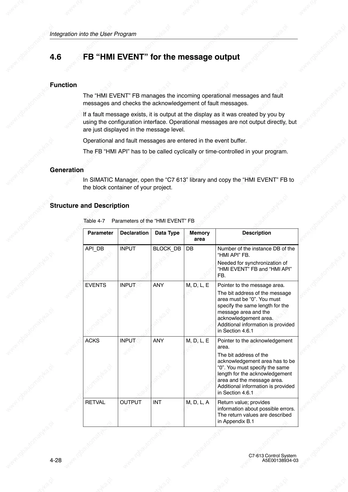
Table 4-7 Parameters of the “HMI EVENT” FB
Parameter
Declaration Data Type Memory
area
Description
API_DB INPUT BLOCK_DB DB Number of the instance DB of the
“HMI API” FB.
Needed for synchronization of
“HMI EVENT” FB and “HMI API”
FB.
EVENTS INPUT ANY M, D, L, E Pointer to the message area.
The bit address of the message
area must be “0”. You must
specify the same length for the
message area and the
acknowledgement area.
Additional information is provided
in Section 4.6.1
ACKS INPUT ANY M, D, L, E Pointer to the acknowledgement
area.
The bit address of the
acknowledgement area has to be
“0”. You must specify the same
length for the acknowledgement
area and the message area.
Additional information is provided
in Section 4.6.1
RETVAL OUTPUT INT M, D, L, A Return value; provides
information about possible errors.
The return values are described
in Appendix B.1

Table of Contents

Question and Answer IconNeed help?

Do you have a question about the Siemens SIMATIC C7-613 and is the answer not in the manual?

Siemens SIMATIC C7-613 Specifications

General IconGeneral
BrandSiemens
ModelSIMATIC C7-613
CategoryControl Systems
LanguageEnglish

Summary

Product overview

Design and Structure

Details the physical components and core architecture of the C7-613.

Product Scope and Accessories

Lists the components included in the C7-613 delivery and necessary accessories for operation.

Installing and Wiring the C7-613

Mechanical installation

Provides detailed steps and precautions for physically mounting the C7-613 unit.

Electrical Configuration and Pin Assignment

Details electrical connections and pin assignments for all C7-613 connectors.

Special Features of the C7-613

Operating Mode Selection

Explains how to select and change the operating modes (RUN, STOP, MRES) of the C7-613.

Integration into the User Program

Program Structure

Outlines the structure of programs for integrating HMI functions using FBs and DBs.

Creating Configuration Data

Details the process of creating configuration data for screens, messages, and info texts.

Operating the C7-613

Keyboard

Describes the layout and functions of the C7-613 keyboard, including system and function keys.

Entering Values

Details methods for entering numerical values using function keys or cursor keys.

Messages

Explains how messages (operational, fault, system) are displayed and managed on the C7-613.

Maintenance

Replacing the C7-613

Details the procedure and precautions for replacing a defective C7-613 unit.

Technical data

Technical Specifications for Control System

Lists detailed technical specifications for the C7-613 control system hardware.

Technical Specifications for CPU

Provides detailed technical specifications for the CPU module used in the C7-613.

Technical Specifications for Integrated I/O

Details the technical specifications for the C7-613's integrated digital and analog input/output modules.

Error Information for HMI FBs and System Messages

Error Information for HMI FBs

Provides information on error codes for HMI Function Blocks (FBs) and their causes/remedies.

System Messages

Lists and explains system messages, their causes, and potential remedies.

Configuration DBs

Configuration DB “CONFIG”

Details the structure and content of the "CONFIG" database for system configuration.

Process screen DB “SCREEN”

Outlines the structure of the "SCREEN" database used for storing process screen definitions.

Related product manuals