EasyManua.ls Logo

Siemens SIMATIC C7-613 User Manual

Siemens SIMATIC C7-613
200 pages
To Next Page IconTo Next Page
To Previous Page IconTo Previous Page
Page #85 background imageLoading...
Page #85 background image
Integration into the User Program
4-29
C7-613 Control System
A5E00138934-03
4.6.1 Operational Messages and Fault Messages
Triggering Messages
Messages are triggered by setting a bit in the message area. The position of the
message area is specified with the “EVENTS” parameter.
Message Area
A message area can be specified for messages 1 to 127.
As soon as the bit is set in the message area and the “EVENT” FB has been run,
the fault/operational message is entered as “arrived” in the event buffer. In
addition, flashing fault messages appear on the display.
After resetting the same bit, the message is recorded as “gone”.
There is no message area and no message bit for Message 0 (idle message).
Assignment of Message Bit and Message Number
A bit in the message area belongs to each message. The bits are assigned
automatically to message numbers in ascending order.
A message bit cannot be assigned to an idle message (message number 0).
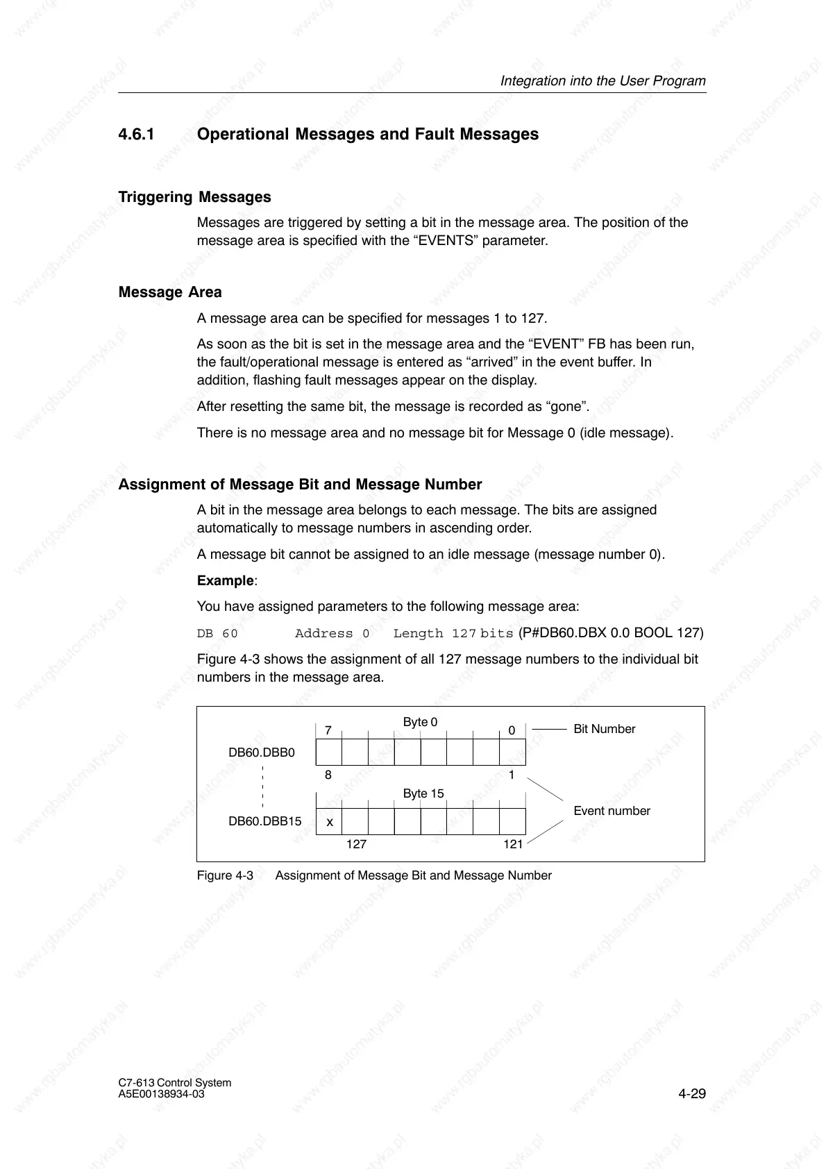
Example:
You have assigned parameters to the following message area:
DB 60 Address 0 Length 127 bits (P#DB60.DBX 0.0 BOOL 127)
Figure 4-3 shows the assignment of all 127 message numbers to the individual bit
numbers in the message area.
127
1
DB60.DBB0
8
DB60.DBB15
7
0
121
Byte 0
Event number
Byte 15
Bit Number
x
Figure 4-3 Assignment of Message Bit and Message Number

Table of Contents

Question and Answer IconNeed help?

Do you have a question about the Siemens SIMATIC C7-613 and is the answer not in the manual?

Siemens SIMATIC C7-613 Specifications

General IconGeneral
BrandSiemens
ModelSIMATIC C7-613
CategoryControl Systems
LanguageEnglish

Summary

Product overview

Design and Structure

Details the physical components and core architecture of the C7-613.

Product Scope and Accessories

Lists the components included in the C7-613 delivery and necessary accessories for operation.

Installing and Wiring the C7-613

Mechanical installation

Provides detailed steps and precautions for physically mounting the C7-613 unit.

Electrical Configuration and Pin Assignment

Details electrical connections and pin assignments for all C7-613 connectors.

Special Features of the C7-613

Operating Mode Selection

Explains how to select and change the operating modes (RUN, STOP, MRES) of the C7-613.

Integration into the User Program

Program Structure

Outlines the structure of programs for integrating HMI functions using FBs and DBs.

Creating Configuration Data

Details the process of creating configuration data for screens, messages, and info texts.

Operating the C7-613

Keyboard

Describes the layout and functions of the C7-613 keyboard, including system and function keys.

Entering Values

Details methods for entering numerical values using function keys or cursor keys.

Messages

Explains how messages (operational, fault, system) are displayed and managed on the C7-613.

Maintenance

Replacing the C7-613

Details the procedure and precautions for replacing a defective C7-613 unit.

Technical data

Technical Specifications for Control System

Lists detailed technical specifications for the C7-613 control system hardware.

Technical Specifications for CPU

Provides detailed technical specifications for the CPU module used in the C7-613.

Technical Specifications for Integrated I/O

Details the technical specifications for the C7-613's integrated digital and analog input/output modules.

Error Information for HMI FBs and System Messages

Error Information for HMI FBs

Provides information on error codes for HMI Function Blocks (FBs) and their causes/remedies.

System Messages

Lists and explains system messages, their causes, and potential remedies.

Configuration DBs

Configuration DB “CONFIG”

Details the structure and content of the "CONFIG" database for system configuration.

Process screen DB “SCREEN”

Outlines the structure of the "SCREEN" database used for storing process screen definitions.

Related product manuals