Integration into the User Program
4-22
C7-613 Control System
A5E00138934-03
4.5.1 LED Activation (LEDS)
Use
The LEDs in the C7-613 function keys can be activated from the user program.
This makes it possible, for example, to signal to the operator with an illuminated
LED which key he is supposed to press, depending on the situation.
Transfer
The LED image is updated each time the “HMI API” FB is called. If the C7-613 is in
STOP mode, the LEDs are switched off.
Structure
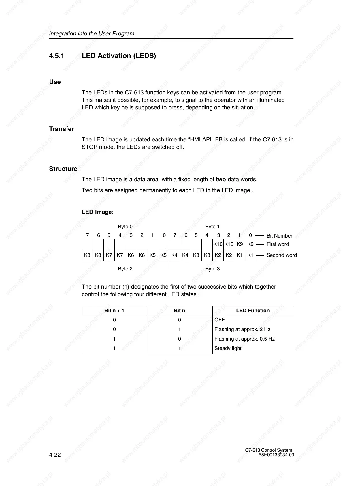
The LED image is a data area with a fixed length of two data words.
Two bits are assigned permanently to each LED in the LED image .
LED Image:
K9
Bit Number
Byte 3
7654321076543210
K1K1K2K2
K9K10K10
K3K3K4K4K5K5K6K6K7K7K8K8
First word
Second word
Byte 1
Byte 2
Byte 0
The bit number (n) designates the first of two successive bits which together
control the following four different LED states :
Bit n + 1 Bit n LED Function
0 0 OFF
0 1 Flashing at approx. 2 Hz
1 0 Flashing at approx. 0.5 Hz
1 1 Steady light

 Loading...


