5
5.2 ”Speed setpoint” mode (P700 = 1) (from SW 2.0)
5-136
Siemens AG 2013 All Rights Reserved
SIMODRIVE POSMO A User Manual (POS1) – 08/2013 Edition
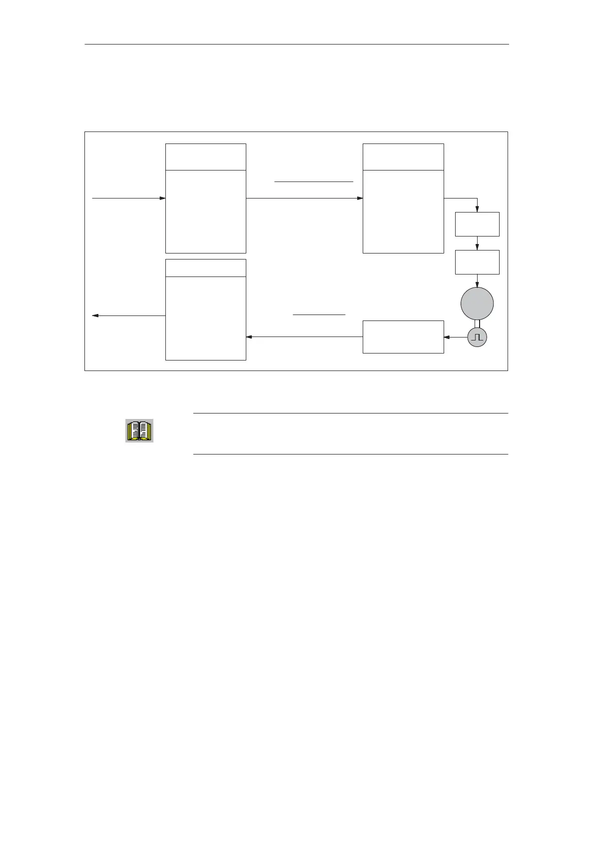
The speed setpoint and the speed actual feedback value are trans-
ferred using PZD data.
Input, n–set
(PZD2)
7FFF
hex
...
1000
hex
(= P880)
...
0000
hex
...
8000
hex
PROFIBUS–DP
(STW)
PROFIBUS–DP
(ZSW)
Act. value (PZD2)
7FFF
hex
...
1000
hex
(= P880)
...
0000
hex
...
8000
hex
Limiting (P8)
np =
If +/– np
is greater/less
than +/– P8
––> limit
to +/– P8
Ramp–up
generator
Speed
setpoint
M
Speed actual
value
nact =
(
hex
)
Primary speed
setpoint:
Hex value to feed back
the speed actual value:
PZD2
P880 P3
4096
nact 4096
P880 P3
Fig. 5-1 Transfer, speed setpoint/actual value
Reader’s note
PZD data, refer to Chapter 4.2.
5.2.2 Ramp–function generator
The ramp–function generator is used to limit the acceleration when the
speed setpoint changes as a step function.
POSMO A transfers the speed setpoint from the DP master to the
ramp–function generator as soon as it is in a specific state of the
PROFIBUS state machine (refer to Chapter 4.2.2).
At run–up, the software limit switches are automatically de–activated
(P6 = P7) and a rotary axis parameterized. In this case, P1 is set to the
maximum value which corresponds to the parameterized values P2 and
P3.
P1 may not be set to zero in ”speed setpoint” mode so that no more
traversing range limits can be activated. Referencing is not possible.
Transmission
elements
General
How do the
software limit
switches function?
5 Description of the Functions
02.9905.03
 Loading...