2
2.4 Mounting SIMODRIVE POSMO A
2-55
E Siemens AG 2013 All Rights Reserved
SIMODRIVE POSMO A User Manual (POS1) – 08/2013 Edition
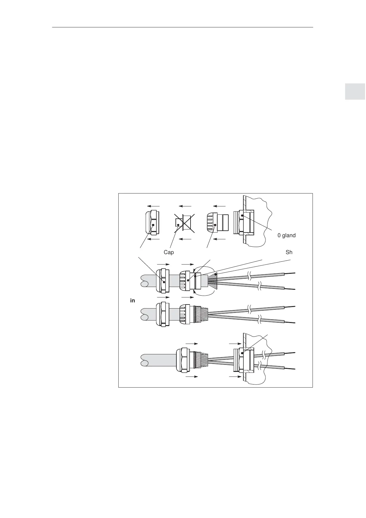
2.4.3 Mounting the prepared cables in the connection cover
The following sequence should be maintained when installing the pre-
pared cables into the connection cover (refer to Fig. 2-24):
1. Release the nut, dummy plugs and terminal insert/seal from the
PG gland.
2. Locate the nut and clamping insert/seal onto the cable.
3. Open–up the shield braiding (remove the insulating foil below).
The shield must cover the O ring by approx. 2 mm.
Cleanly cut–off excessive shield!
4. Assemble the nut with clamping insert/seal.
5. Insert these into the PG gland and tighten the nut.
6. Connect the ends of the cables to the lower side of the connection
cover.
Clamping insert/sealNut
Shield
Connection to the PROFIBUS unit
O ring
M20 gland
M20 gland
Cap
Point 1
Point 3
Point 4
Point 5
Point 2
Point 3
Wiring at
X20
Point 6
Fig. 2-24 How are the prepared cables installed?
How are the
prepared cables
installed?
2 Installing and Connecting–Up
02.99
 Loading...