2
2.3 Connection and wiring overview
2-43
E Siemens AG 2013 All Rights Reserved
SIMODRIVE POSMO A User Manual (POS1) – 08/2013 Edition
2.3 Connection and wiring overview
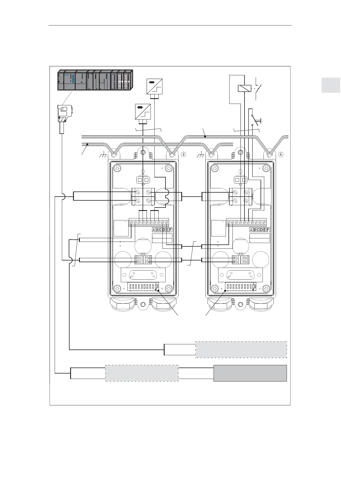
1VS
I/Q1
1M
2VS
I/Q2
2M
3M
3L+
4L+
4M
L1
X6
X2
5M
5L+
6L+
6M
X5
B1A1
B2A2
X3
X4
S1
X7
X1
X9
1VS
I/Q1
1M
2VS
I/Q2
2M
3M
3L+
4L+
4M
L1
X6
X2
5M
5L+
6L+
6M
X5
B1A1
B2A2
X3
X4
S1
X7
X1
X9
e.g. relay
Load power supply
(e.g. SITOP power)
Power Management Module
(DC–PMM) (optional)
+24 V/48 V
Chassis
ground
A cable
B cable
e.g. SIMATIC S7–300 DP
PROFIBUS interface
24 V electronics power supply
(e.g. SITOP power) (optional)
+24 V
Chassis
ground
+24 V
Chassis
ground
S Last node (here, to the right) ––> switch–in the terminating resistor (refer to Chapter 2.3.1)
S Set the PROFIBUS node address for the slaves (refer to Chapter 2.3.1)
e.g. relay
e.g. switch
e.g. BERO 1
e.g. BERO 2
+24 V/48 V
Chassis
ground
Protective conductor (PE)
1)
(refer to Chapter 2.3.2)
Potential
bonding
conductor (refer
to Chapter 2.3.2)
First node
(in this case, the master)
––>
switch in the terminating
resistor
+24 V/48 V
Chassis
ground
1) The protective conductor may not be interrupted (refer to Chapter 2.3.2)
Note:
Use only copper cables with a thermal stability of up to at least 60/75°C. for connection and wiring.
Fig. 2-13 Connection and wiring overview (example with DC PMM and electronics power supply)
2 Installing and Connecting–Up
02.9908.0305.13
 Loading...