2
2.2 Electrical system requirements
2-31
E Siemens AG 2013 All Rights Reserved
SIMODRIVE POSMO A User Manual (POS1) – 08/2013 Edition
S When using a contactor in the load power supply, before opening
the contactor, it must be ensured that the pulses have been can-
celed via PROFIBUS (OFF 1).
S All of the power supplies must have ”protective separation”.
S When using SIMODRIVE POSMO A in UL–certified systems, a UL–
certified varistor with the following properties is required in the
power supply cable:
24 V ––> V
N
= 31 V DC, I
max
= 2000 A
e.g. SIOV–S20–K30 from EPCOS
48 V ––> V
N
= 65 V DC, I
max
= 6500 A
e.g. SIOV–S20–K50 from EPCOS
This circuit is not required when using the DC–PMM (refer to Chap-
ter 2.2.3).
S When using POSMO A – 300 W in the temperature range
–20...0 _C it should be ensured that all of the system components
are certified for this temperature range.
2.2.2 DC power supply (24 V, 48 V)
The load power supply must be dimensioned as a function of the num-
ber of positioning motors SIMODRIVE POSMO A and the coincidence
factor.
Note
If possible, the load power supply should be switched–in/switched–out
on the primary side.
If this is not possible for technical reasons, a power management
module (DC PMM) must be connected between the switch element
and the SIMODRIVE POSMO A, refer to Chapter 2.2.3.
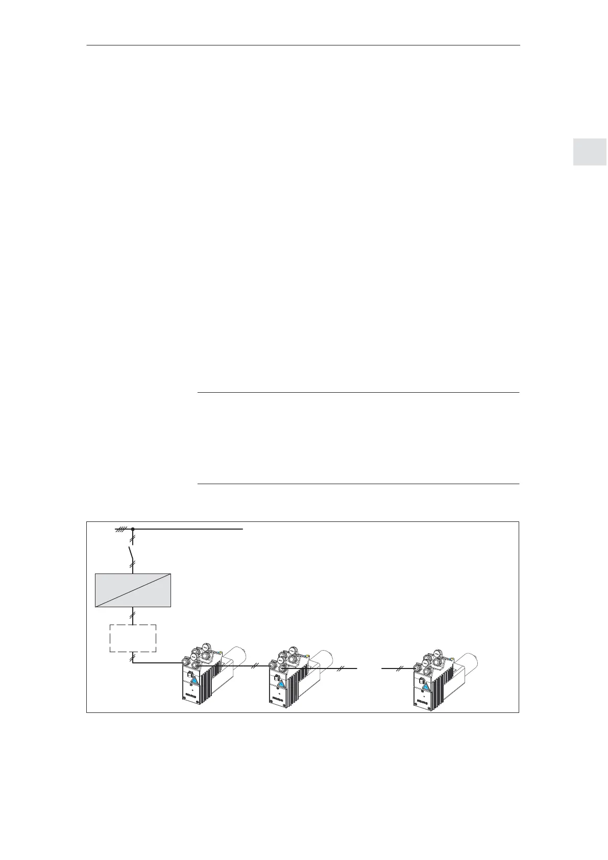
S Switching–in and switching–out the 24 V/48 V load power supply on
the primary side (line–specific)
DC–PMM
SIMODRIVE
POSMO A
Optional, according to Chapter 2.2.3
Line
supply
Contactor
. . .
e.g. SITOP
24 V/48 V
400 V
Fig. 2-2 Switching–in and switching–out the 24 V/48 V on the primary side
General
information on the
power supply
2 Installing and Connecting–Up
02.9906.0505.13
 Loading...