02.00 Connections
Siemens AG 6RX1700-0AD76 6-15
SIMOREG DC Master Operating Instructions
6.1.3 Information on line-side harmonics generated by converters in a
fully-controlled three-phase bridge circuit configuration B6C and (B6)A(B6)C
Converters for the medium power range usually consist of fully-controlled three-phase bridge circuit
configurations. An example of the harmonics generated by a typical system configuration for two
firing angles (α = 20° and α = 60°) is given below.
The values have been taken from an earlier publication entitled "Harmonics in the Line-Side Current
of Six-Pulse Line-Commutated Converters" written by H. Arremann and G. Möltgen, Siemens
Research and Development Dept., Volume 7 (1978) No. 2, Springer-Verlag 1978.
Formulae have been specified with which the short circuit power
S
K
and armature inductance
L
a
of
the motor to which the specified harmonics spectrum applies can be calculated depending on the
applicable operating data [line voltage (no-load voltage
U
v0
), line frequency
f
N
and DC current
I
d
].
A dedicated calculation must be performed if the actual system short circuit power and/or actual
armature reactance deviate from the values determined by this method.
The spectrum of harmonics listed below is obtained if the values for short circuit power
S
K
at the
converter supply connection point and the armature inductance
L
a
of the motor calculated by the
following formulae correspond to the actual plant data. If the calculated values differ, the harmonics
must be calculated separately.
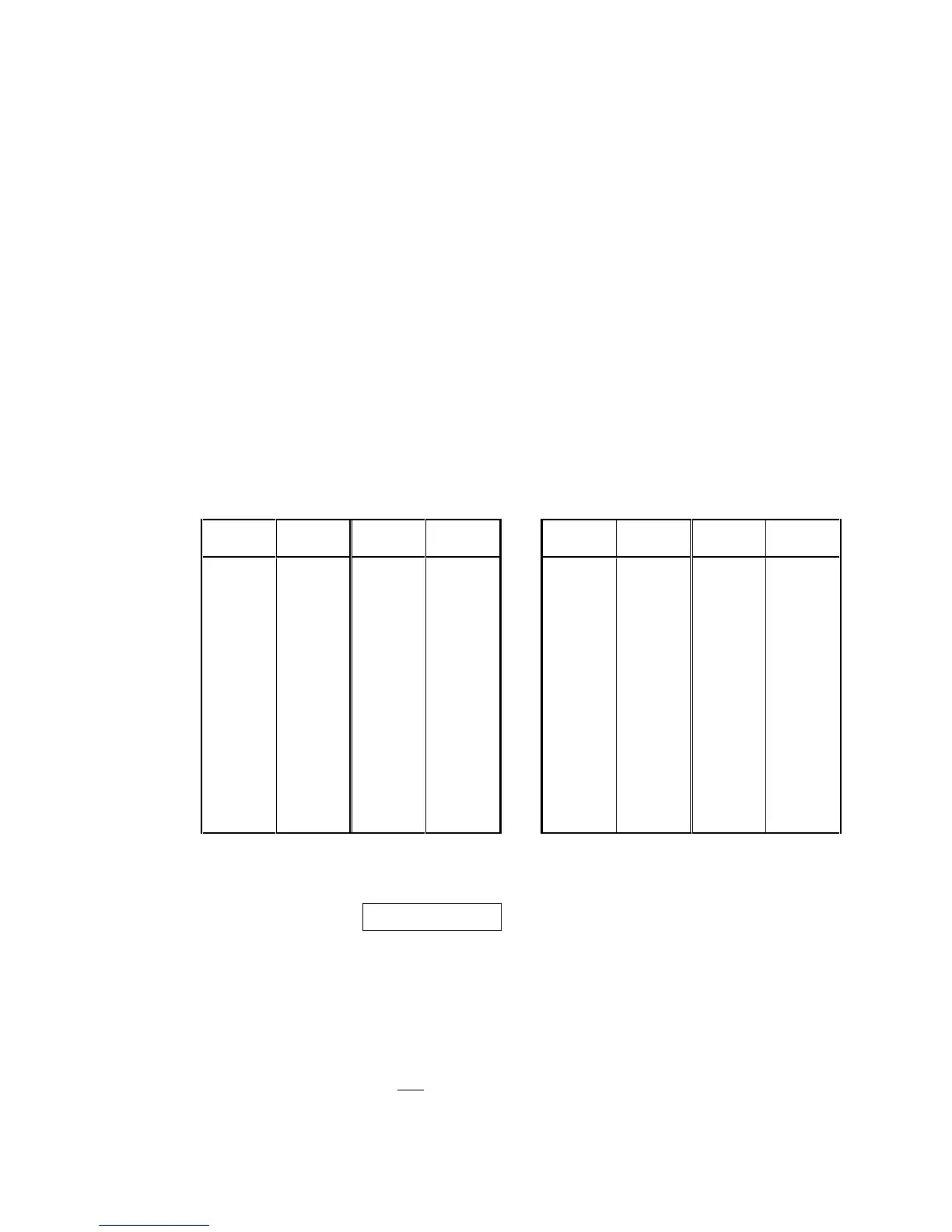
a.) α = 20° b.) α = 60°
Fundamental factor
g
= 0.962 Fundamental factor
g
= 0.953
ν
I
ν
/
I
1
ν
I
ν
/
I
1
ν
I
ν
/
I
1
ν
I
ν
/
I
1
5 0.235 29 0.018 5 0.283 29 0.026
7 0.100 31 0.016 7 0.050 31 0.019
11 0.083 35 0.011 11 0.089 35 0.020
13 0.056 37 0.010 13 0.038 37 0.016
17 0.046 41 0.006 17 0.050 41 0.016
19 0.035 43 0.006 19 0.029 43 0.013
23 0.028 47 0.003 23 0.034 47 0.013
25 0.024 49 0.003 25 0.023 49 0.011
The fundamental-frequency current
I
1
as a reference quantity is calculated by the following
equation:
d1
0.817 II ××=
g
where
I
d
DC current of operating point under investigation
where
g
Fundamental factor (see above)
The harmonic currents calculated from the above tables are valid only for
I.) Short-circuit power
S
K
at converter supply connection point
()
S
U
 Loading...


