02.00 Connections
Siemens AG 6RX1700-0AD76 6-17
SIMOREG DC Master Operating Instructions
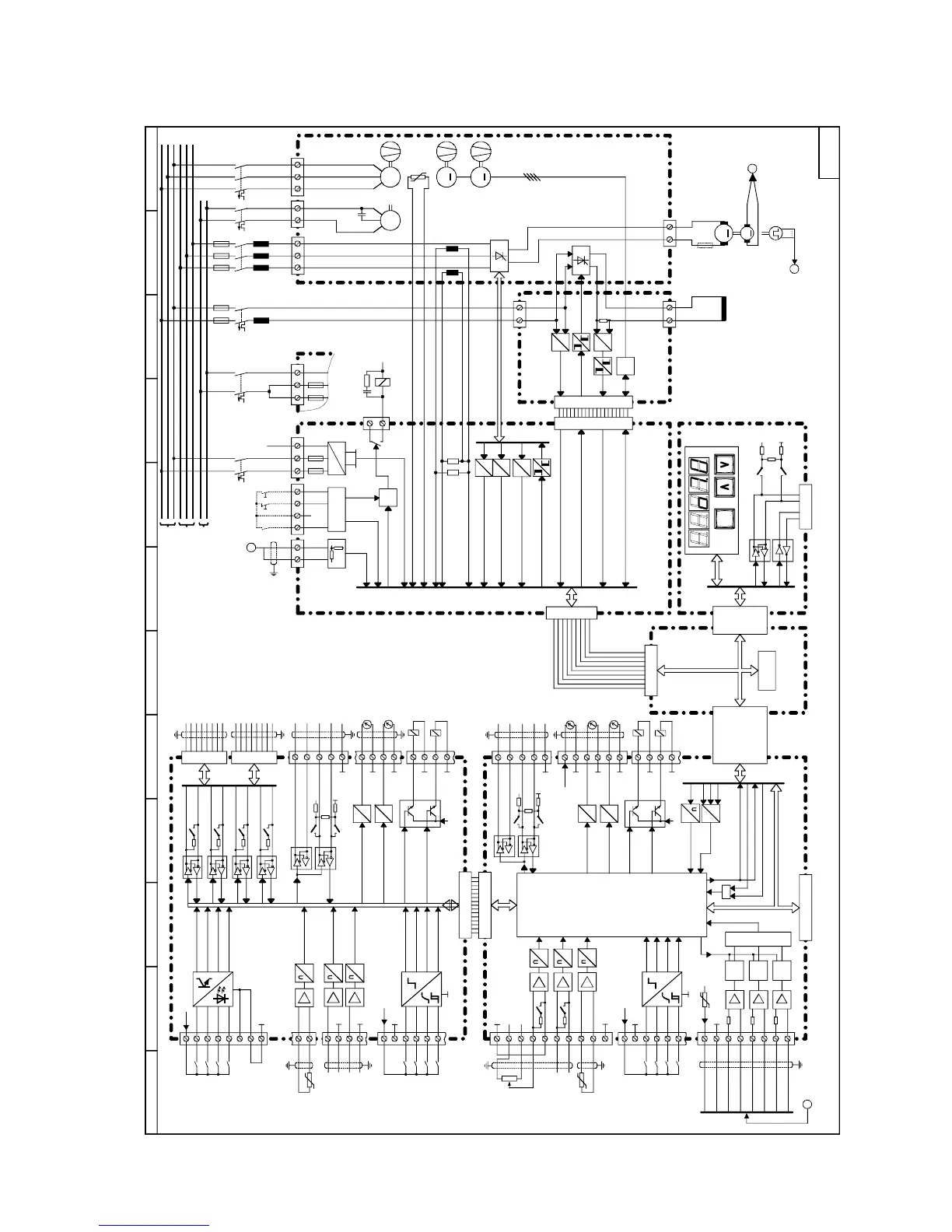
6.2 Block diagram with recommended connection
123456789101112
103
104
ES/
P24
E-Stop
105
106
107
108
8-270V
M
3AC 50-60Hz, 400V-830V
3AC 50-60Hz, 400V-460V
1U1
1V1
1W1
3U1 3W1
5U1
5W1
=
∼
K1
4U1
4V1
4W1
M
~
2
M
G
1
1C1
(1D1)
1D1
(1C1)
∼
∼
∼
∼
∼
∼
=
=
f
U
3D 3C
1
2)
M
3)
X101
X102
C98043-A7002 / A7003
C98043-A7004 /
C98043-A7010 /
C98043-A7014+15
PMU
OP1S
X300
C98043-A7005
X102
X75
X11-X16
X21-X26
X6
X7
X3.4
X3.1
X3.2
X3.3
XT
XS
XP
+
-
5N1
NC
34
37
38
39
36
35
COMP
X > Y
P15
M
26
27
28
29
30
31
32
33
200mA max.
54
46
47
48
D
A
D
A
M
M
14
15
16
17
12
13
M
10k
M
P10 ± 1% / 10 mA
1
2
3
4
5
6
7
N10 ± 1% / 10 mA
22
23
Tx+
Tx-
Rx+/Tx+
Rx-/Tx-
RS485
M
COMP
X > Y
COMP
X > Y
=
∼
2
C98043-A7001
X109
56
57
58
59
60
X107
X110 / X111
CUD1
M
24
M
M
P24
M
M
&
X108
X101
C98043-A7009
45
40
41
42
43
50
51
52
M
M
8
9
10
11
D
A
D
A
M
M
18
19
20
21
211
212
213
214
215
210
204
205
P24_S
#
KTY84 / PTC
Tx+
Tx-
Rx+/Tx+
Rx-/Tx-
RS485
M
+
M
Rx+/Tx+
Rx-/Tx-
61
62
63
64
65
44
53
C98043-A7006
4)
X110 / X111
CUD2
Rx+/Tx+
Rx-/Tx-
Rx+/Tx+
Rx-/Tx-
Rx+/Tx+
Rx-/Tx-
P24
M
M
S_IMP
T/R
R/T
Clk
M
M
M
217
216
X165
X166
EEPROM
KTY84 / PTC
110
109
K1
XR
K1
#
#
#
#
#
#
RS485
RS232
P24_S
4)
P24_S
4)
X161
X164
X164
X164
X163
X163
X162
X174
X171
X173
X171
X175
X172
5/15V
XF1
XF2
M
3)
BA
BA
BA
BA
BA
BA
M
+
BA
BA
U/I
U/I
M
+
BA
BA
5U1
5W1
XP
5N1
1AC 50-60Hz, 230V
M
1
~
4U1
4N1
1)
Shunt
Load
Analog
tacho
E-Stop
Electronics power supply
Armature current
Temperature monitoring
Supply voltage
armature
Armature voltage
Supply voltage field
Field current actual value
Gating pulses armature
Gating pulses field
Fan control
and monitoring or
air flow monitoring
Fan control and monitoring
2) Into converters
≥
450A to 850A, 460V (X01)
3) Into converters 210 to 280A
4) P24_S total max. 200mA
to
-
Switch-on/
shutdown
Enable signal
Track 1
>
Track 2
>
Zero mark >
Supply
Main
setpoint
Open- and
closed-loop
control for
armature
and field
Armature current
Analog tacho
Rear panel wiring
Motor
temperature
Binary
select inputs
Binary
select inputs
Parallel switch
interface
(2x)
Power ON
Selection
BA = electronically switchable bus termination
U/I = electronically switchable voltage /
current input
RS232 / RS485 to X300
I act
or
TB and CB boards
1) Into converters
≥ 400A
or
 Loading...


