9.1.3 LED displays of the Ethernet interface
The Ethernet ports are equipped with LEDs to display Link and Activity.
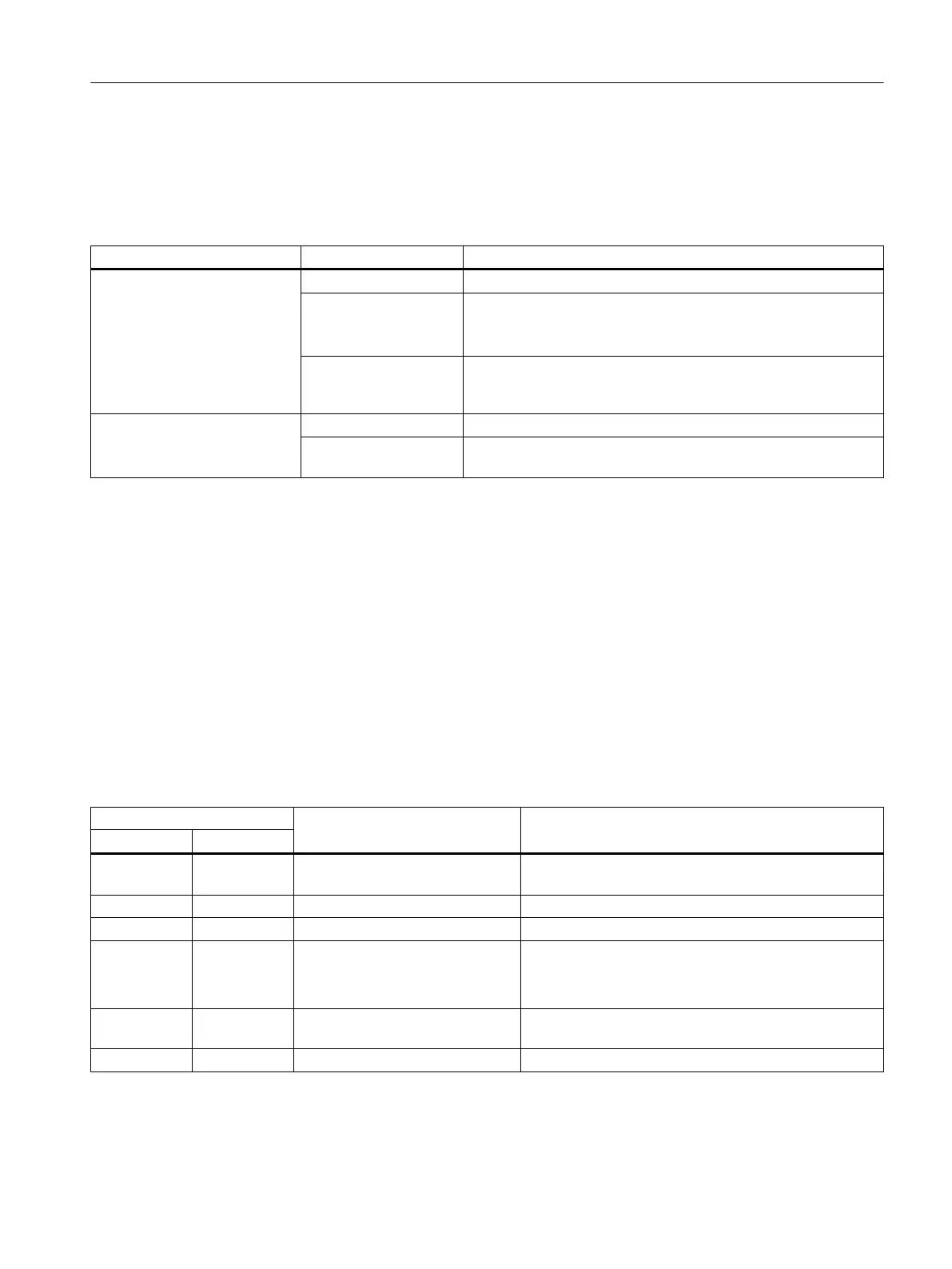
Table 9-3 State of the Link and Activity LEDs
LED State Meaning
LINK (upper LED) OFF No or faulty connection
Lights up green Transfer rate 10 or 100 Mbit/s:
A
different device is connected to port x and a physical connection
exists
Lights up yellow Transfer rate 1,000 Mbit/s:
A
different device is connected to port x and a physical connection
exists
ACT (lower LED) OFF No data exchange
Flickers yellow Data exchange:
Data is being received or sent at port x
9.1.4 LED displays of the CX32-2 controller extension
The different states that occur during power-up are indicated by the LEDs on the CX32-2
controller extension.
●
The duration of the individual states varies.
● If an error occurs, the power-up is terminated and the cause is indicated accordingly via
the LEDs.
● At the end of an error-free power-up, all LEDs are switched off briefly.
● After power-up, the LEDs are controlled via the loaded software.
Table 9-4 Load software
LED State Comment
RDY DP
Yellow Yellow Reset Hardware reset
All other LEDs light up yellow
Red Red BIOS loaded -
Red 2 Hz Red BIOS error Error occurred while loading the BIOS
Red 2 Hz Red 2 Hz File error
● D4x5‑2 CompactFlash card not available or faulty
●
Software on D4x5‑2 CompactFlash card not
available or faulty
Red Yellow (flash‐
ing)
FW loading RDY LED lights up red, DP LED flashes yellow without
fixed frequency
Red Off FW loaded -
Diagnostics
9.1 Diagnostics via LED displays
SIMOTION D4x5-2
Commissioning and Hardware Installation Manual, 03/2018, A5E33441636B 393

 Loading...


