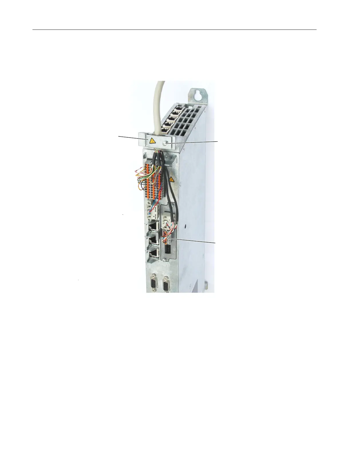
Shield connection for TB30
The
following figure shows the cable routing, cable connection and the connection of the I/Os
on the TB30. The TB30 is inserted in a CU320-2 here.
6KLHOGOXJIRU
FRQQHFWLQJWKHFDEOH
VKLHOGV
6FUHZ
01P
7RU[7
;
'LJLWDOLQSXWVRXWSXWV
Figure 4-10 Shield connection for TB30 using the digital I/Os as an example
The arrangement is similar when inserted in a D4x5-2, see also Section Creating a shield
connection (Page 72) for more details.
The permissible bending radii for the cables must be maintained when the cables are being
laid.
Connecting
4.6 Connecting I/Os
SIMOTION D4x5-2
Commissioning and Hardware Installation Manual, 03/2018, A5E33441636B 75

 Loading...


