3. Remove a sufficient length of the cable sheath at the control end so that you can connect
the shield to the shield connecting element and the free cable ends to the front connector.
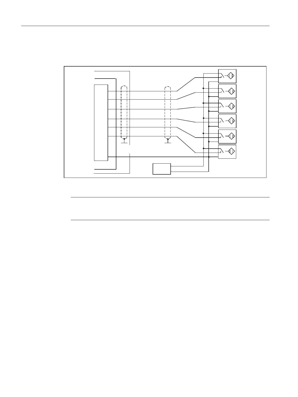
4. Wire the signal line to the front connector.
6KLHOGURXWHGRQVKLHOGFRQQHFWLQJ
HOHPHQW
/
0
H[WHUQ
;
6,027,21&
Figure 6-17 Overview of connections for measuring inputs or proximity encoders
Note
For the assignment of the front connector and the description of the I/O interface, refer to
chapter I/O interface (Page 69).
Connection of additional actuators/encoders
If you wish to connect additional actuators/encoders to the SMs on the I/O bus, proceed in the
same way as for connecting digital inputs/digital outputs to the SIMATIC S7-300.
See the
S7-300, M7-300 Automation Systems, Module Data
Manual.
The digital inputs/digital outputs on the central I/O system are recorded/output at a refresh rate
of approx. 1 ms.
6.1.8 Connecting shielded cables via a shield connecting element
Application
With the shield connecting element, you can easily connect all the shielded wires of the
SIMOTION C or S7 modules to ground by directly connecting the shield connecting element
with the mounting rail.
Connecting
6.1 Wiring
SIMOTION C
116 Operating Instructions, 11/2016, A5E33441428B

 Loading...


