Installation sequence
The individual steps for the installation of the modules are described below:
1. Except for the SIMOTION C, each signal module is supplied with a bus connector. When
plugging in the bus connectors, always start with the SIMOTION C.
Take the bus connector from the next module and plug it into the bus connector of the
SIMOTION C. (The bus connector is located on the rear side, see Figure "Position of
interfaces and front panel elements").
You must not plug a bus connector into the "last" module in the row.
2. Fit the modules by hooking them into position, push them against the left-hand module and
lower them down into position.
3. Screw down the modules, applying a torque of 0.8 to 1.1 Nm.
5.3.3 After installation
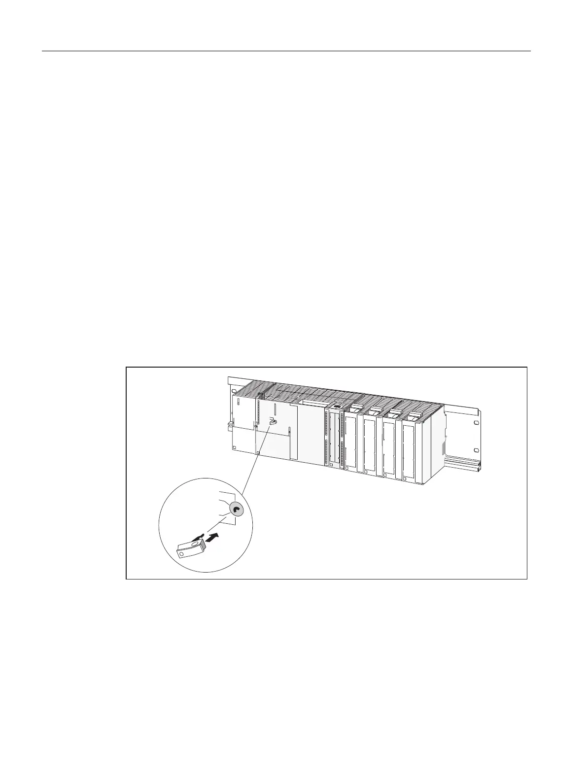
Inserting the key (C230-2)
Once the C230-2 has been mounted on the mounting rail, you can insert the key in the STOP
or STOPU position on the C230-2.
Figure 5-7 Inserting the key in the C230-2
Configuring and installing
5.3 Installing
SIMOTION C
86 Operating Instructions, 11/2016, A5E33441428B

 Loading...


