4.6 Onboard measuring system interface (C230-2, C240)
Connectors to the encoder
A 15-pin Sub-D socket for the connection of incremental or absolute encoders (SSI) is provided
for each axis.
With the C240, this interface (X3 to X6) can also be used as a counter input.
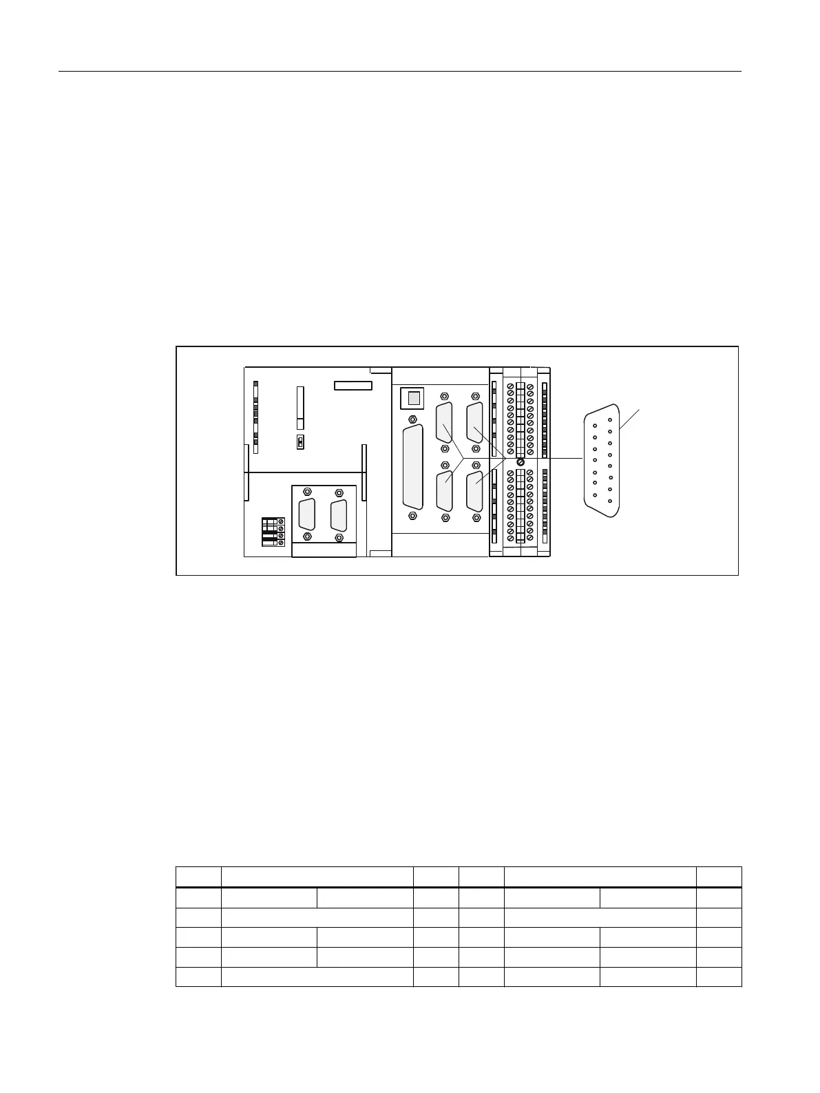
Position of connectors
This figure shows the mounting position and the designation of the connector on the module.
(1&2'(5
(1&2'(5
;;
;
;;
;;
;
;'303,;'3
&
6,(0(16
;
05(6
6723
581
Figure 4-8 Position of connectors X3 to X6
Connector pin assignment
Designation:
X3, X4, X5, X6 - ENCODER 1 to 4
Assignment of ENCODER - axis channel:
X3 - axis channel 1
X4 - axis channel 2
X5 - axis channel 3
X6 - axis channel 4
Type: 15-pin Sub-D socket connector
Table 4-9 Assignment of connectors X3 to X6
Pin Encoder Type Pin Encoder Type
Incremental Absolute Incremental Absolute
1 Not assigned 9 MEXT VO
2 CLS O 10 Z I
3 CLS_N O 11 Z_N I
4 P5EXT VO 12 B_N I
Interfaces
4.6 Onboard measuring system interface (C230-2, C240)
SIMOTION C
56 Operating Instructions, 11/2016, A5E33441428B

 Loading...


