Signal names
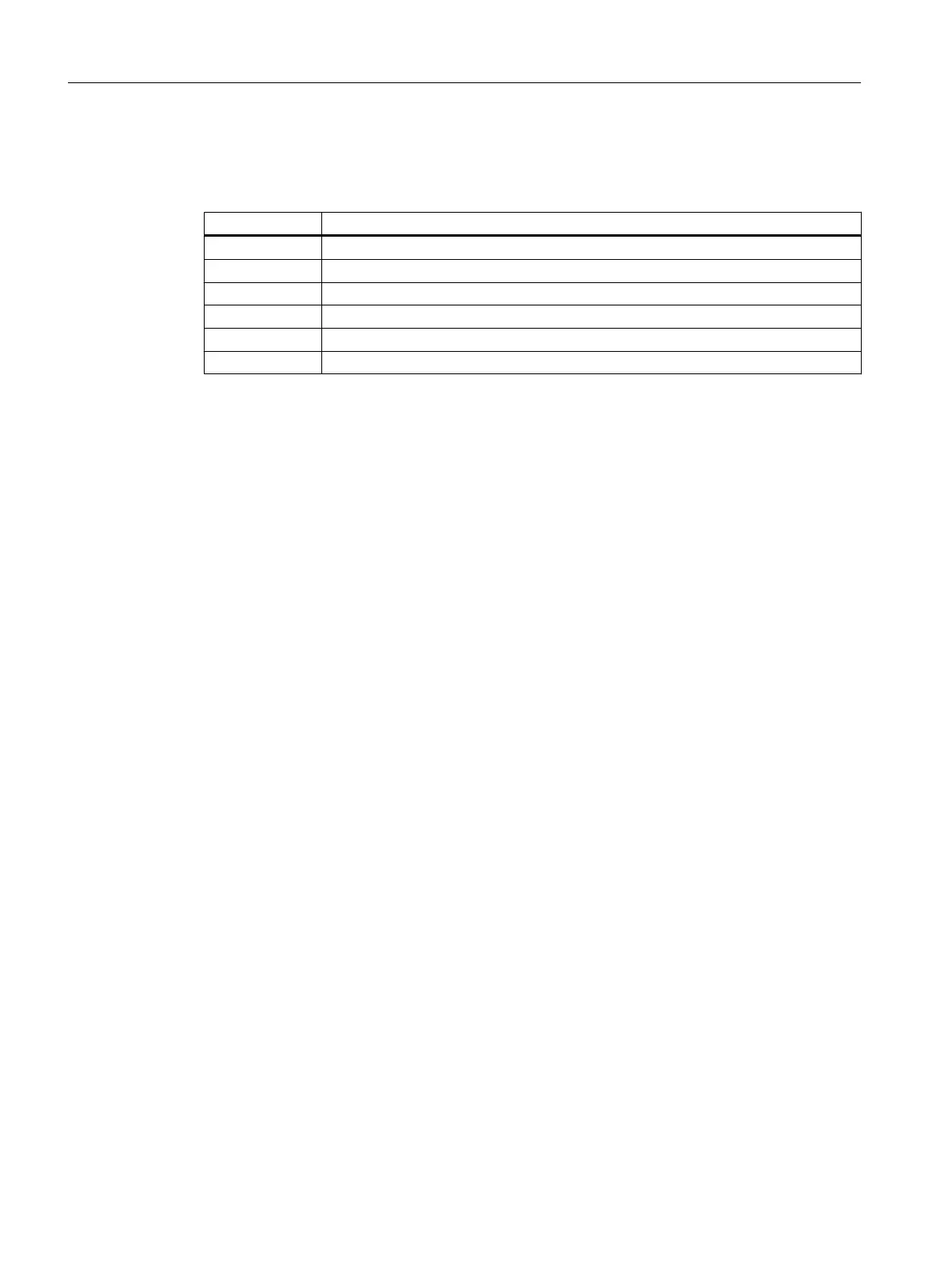
Table 4-5 Signal names
Signal name Meaning
A, B Data input/output (RS485)
RTS Transmission request
P5 5 V power supply 60 mA, short-circuit-proof
M5 5 V reference potential
P24 24 V supply 150 mA, short-circuit-proof, not isolated
M24 24 V reference potential
Signal type
O - signal output
I/O - signal input/output
VO - voltage output
4.5 Onboard drive interface (C230-2, C240)
Connector to drive unit
Drive units with an analog interface (±10 V) or stepper motor power units with at least one
clock pulse input and direction input can be connected to the 50-pin Sub-D socket X2. Any
hybrid configuration can be used for up to four drives.
In addition, the C230-2 and C240 provide one enable signal per axis.
With the C240, this interface (X2) can also be used for standard outputs:
● 4 analog outputs
● 4 digital outputs
Interfaces
4.5 Onboard drive interface (C230-2, C240)
SIMOTION C
48 Operating Instructions, 11/2016, A5E33441428B

 Loading...


