Clearances
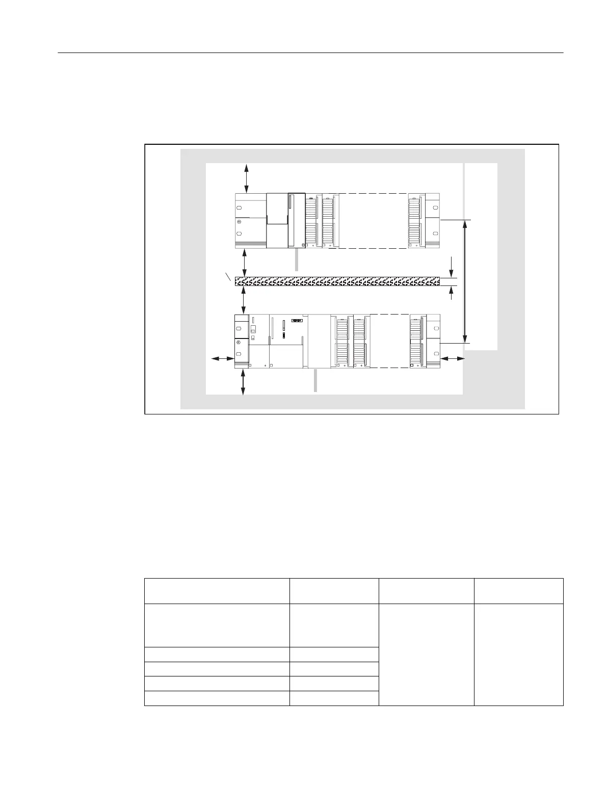
The following figure shows the clearances between the individual racks and the clearance to
adjacent equipment, cable ducts, cabinet walls, etc.
HJFDEOH
FKDQQHO
PP
PP
PP
PP
PP
PP
PP
D
D
Figure 5-2 Clearances
5.2.3 Mounting dimensions of modules
Overview of mounting dimensions
The following table shows the mounting dimensions of modules.
Table 5-1 Mounting dimensions of modules
Modules Module width Module height Maximum
mounting depth
Power supply PS 307, 2 A
Power supply PS 307, 5 A
Power supply PS 307, 10 A
50 mm
80 mm
200 mm
125 mm, 185 mm
with shield connect‐
ing element
130 mm or 180 mm
with an open front
cover of the SIMO‐
TION C
SIMOTION C 200 mm
Signal modules (SMs) 40 mm
Function modules (FM) 40 mm or 80 mm
Communications processors (CP) 40 mm
Configuring and installing
5.2 Configuring an installation using SIMOTION C modules
SIMOTION C
Operating Instructions, 11/2016, A5E33441428B 79

 Loading...


