7.4 Addressing the onboard digital inputs and outputs of the SIMOTION
C
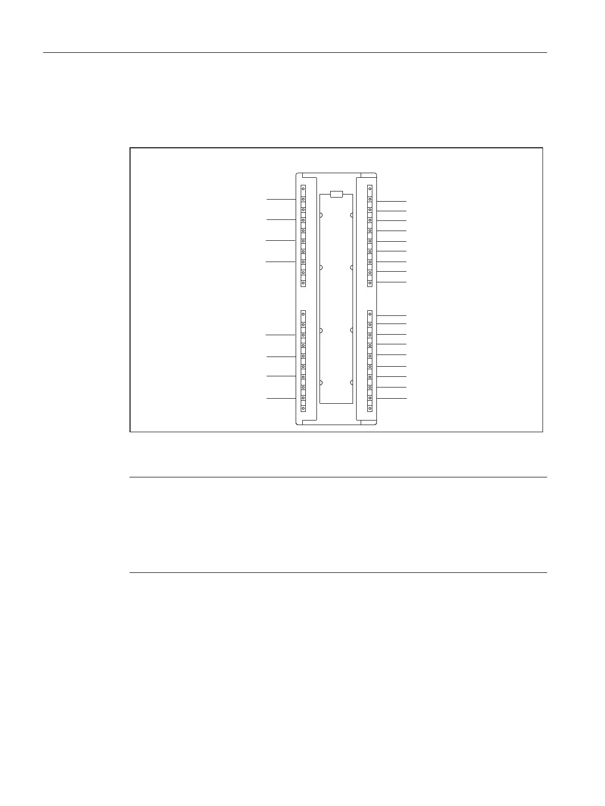
The following figure shows the default start addresses of the onboard digital inputs/outputs.
$GGUHVV$
$GGUHVV$
$GGUHVV$
$GGUHVV$
$GGUHVV$
$GGUHVV$
$GGUHVV$
$GGUHVV$
$GGUHVV(
$GGUHVV(
$GGUHVV(
$GGUHVV(
$GGUHVV(
$GGUHVV(
$GGUHVV(
$GGUHVV(
$GGUHVV(
$GGUHVV(
$GGUHVV(
$GGUHVV(
$GGUHVV(
$GGUHVV(
$GGUHVV(
$GGUHVV(
$GGUHVV(
$GGUHVV(
,QSXWV2XWSXWV
0
%
%
%
%
0
6,027,21&
Figure 7-6 Addressing the onboard digital inputs/outputs
Note
These addresses can be modified by the user in the
hardware configuration
(see SIMOTION
SCOUT online help).
When used by a TO (e.g. measuring input/output cam), the address must be ≥ 64.
All start addresses/signal bits (64.4...64.7, 65.0...65.3, 65.6, 65.7, 67.4...67.7) not listed do not
have any defined values and consequently may not be used for evaluation.
As of SIMOTION V4.2, the onboard digital inputs/outputs of the C240 and C240 PN cannot
only be interconnected with variables via their direct addresses, by also by means of symbolic
assignment.
Addressing
7.4 Addressing the onboard digital inputs and outputs of the SIMOTION C
SIMOTION C
134 Operating Instructions, 11/2016, A5E33441428B

 Loading...


