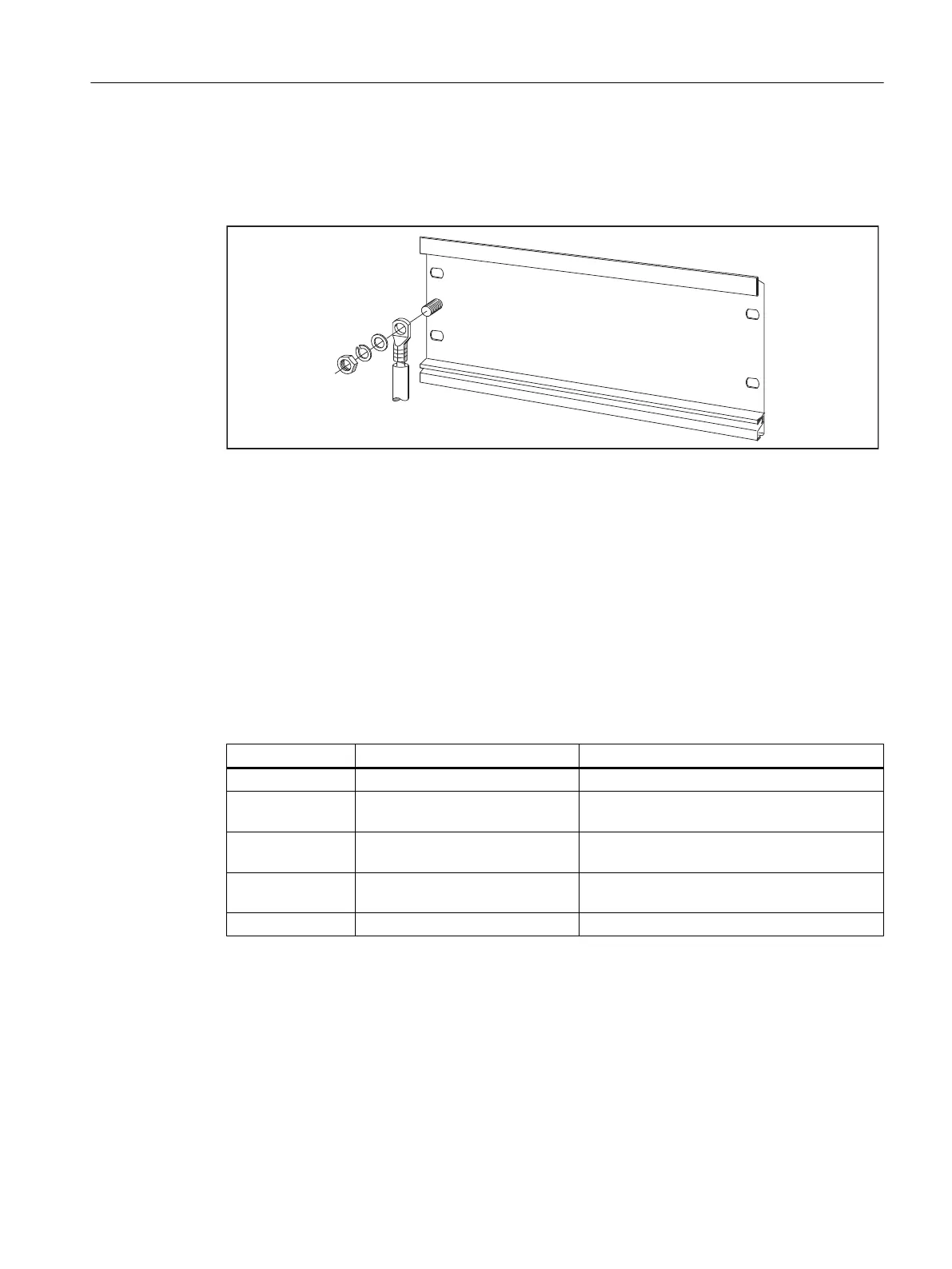
PE connection
The figure below shows the proper way of connecting the protective conductor to the mounting
rail.
Figure 5-6 Protective conductor connection on the mounting rail
5.3.2 Fitting modules on the mounting rail
Accessories
Any accessories you need for installation are in the pack with the modules. Chapter Spare
parts and accessories (Page 173) contains a list of accessories and spare parts together with
the corresponding Article Nos.
Table 5-6 Module accessories
Module Accessories supplied Explanation
SIMOTION C One slot number plate For the assignment of slot numbers
Two keys (C230-2) The key is used to operate the mode selector
for the C230-2.
One labeling plate For labeling of integrated inputs and outputs of
the SIMOTION C
Signal module
(SM)
One bus connector To provide the electrical connections between
the modules
One labeling plate To label the inputs and outputs on the module
Sequence in which modules are affixed to the mounting rail
1. Power supply module
2. SIMOTION C
3. Signal module(s)
Configuring and installing
5.3 Installing
SIMOTION C
Operating Instructions, 11/2016, A5E33441428B 85

 Loading...


