$FWXDOYDOXHODWFKWLPH
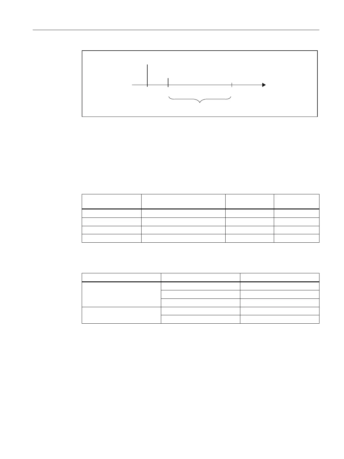
3RVLWLRQFRQWUROF\FOHFORFNWLPH
3RVLWLRQFRQWUROF\FOH
7
L
7
W
Figure 4-12 Position control cycle
Connecting cable to the encoder
The maximum cable length depends on the specification for the encoder supply and the baud
rate. For problem-free operation, you must not exceed the following values when using
SIEMENS preassembled connecting cables (see
Catalogs PM 21/NC 60/ST 70
):
Table 4-14 Maximum cable lengths, depending on the encoder power supply
Supply voltage Encoder supply voltage range Current consump‐
tion
Max. cable length
5 VDC 4.75 V to 5.25 V < 300 mA 25 m
5 VDC 4.75 V to 5.25 V < 210 mA 35 m
24 VDC 20.4 V to 28.8 V < 300 mA 100 m
24 VDC 10 V to 30 V < 300 mA 250 m
Table 4-15 Maximum cable lengths, depending on the baud rate
Encoder type Frequency° Max. cable length
Incremental encoder 1 MHz 10 m
500 kHz 35 m
300 kHz 100 m
Absolute encoder (SSI) 1.5 Mbits/s 10 m
187.5 Kbyte/s 250 m
4.7 Possible uses of onboard drive and measuring system interface in the
application (C230-2, C240)
4.7.1 Overview
The onboard drive interface and the measuring system interface can be used in the application
for the technology objects TO axis and TO externalEncoder, and for I/O variable.
Interfaces
4.7 Possible uses of onboard drive and measuring system interface in the application (C230-2, C240)
SIMOTION C
Operating Instructions, 11/2016, A5E33441428B 65

 Loading...


