8.6 Response times when a monitoring function responds
Response times when limit values are violated
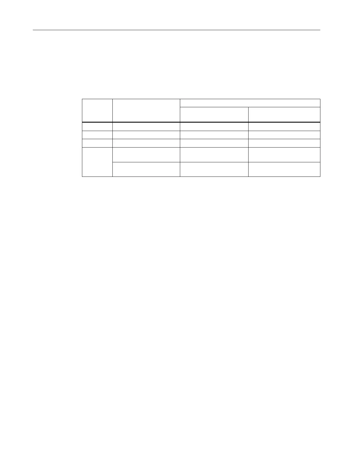
Table 8-10 Response times
Function Response Response times
Worst case for a fault-free
drive system
Worst case when a fault ex‐
ists
SS1 STOP A 67 ms
1)
101 ms
1)
SLS STOP A or STOP B 67 ms
1)
113 ms
1)
SDI STOP A or STOP B 61 ms
1)
107 ms
1)
SSM Signal change in PROFI‐
safe bit S_STW1.7
101 ms
1)
135 ms
1)
Forced checking procedure
of the fail-safe output F_DO:
77 ms
1)
113 ms
1)
1)
Immediately after switching-on the motor, the response times are extended by p9586 (Delay time
actual value sensing).
Response time after PROFIsafe communication interruption
The inverter receives the PROFIsafe monitoring time from the higher-level-level, fail-safe
control (F-CPU).
If the PROFIsafe telegram is not received before the end of the PROFIsafe monitoring time,
the inverter activates the STO function.
Depending when the interruption takes place, the inverter can signal the following faults:
● Basic functions have been enabled: Fault F01611
● Extended functions have been enabled: Message C01711
System properties
8.6 Response times when a monitoring function responds
Safety Integrated - SINAMICS G110M, G120, G120C, G120D and SIMATIC ET 200pro FC-2
Function Manual, 01/2017, FW V4.7 SP6, A5E34261271B AD 379