4.3.6 Application examples
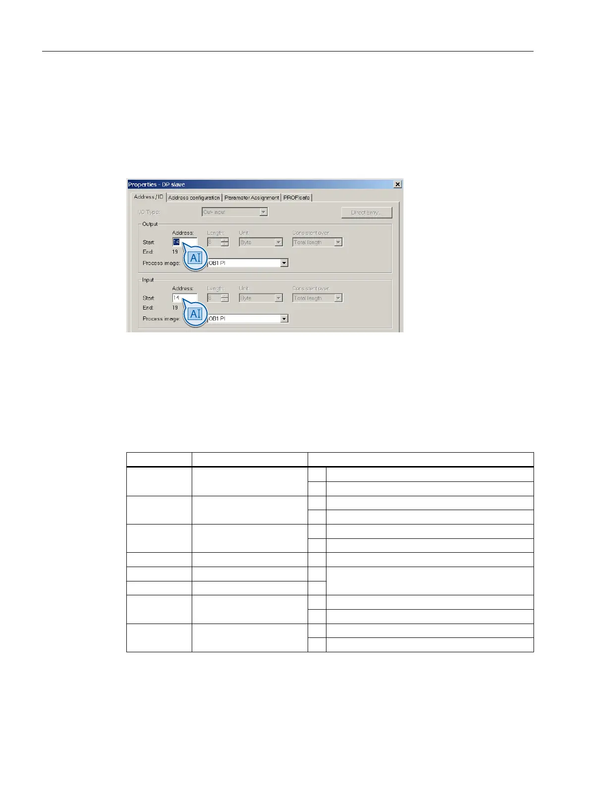
Assigning the inverter to the input and output addresses of the control system
By configuring the higher-level control, you assign the control word and the status word in the
PROFIsafe profile of the inverter to specific input and output addresses in the control.
Figure 4-6 Example: in the control, assign the initial address 14 for the inverter
Control the inverter using the control program
This results in the following assignments between the I/O addresses and inverter signals for
this example:
Table 4-8 Control word 1
I/O address Meaning Comment
A14.0 Select STO 0 Select STO
1 Deselect STO
A14.1 Select SS1 0 Select SS1
1 Deselect SS1
A14.4 Select SLS 0 Select SLS
1 Deselect SLS
A14.7 Internal event ACK - Acknowledge with signal change 1 → 0
A15.1 Select SLS level bit 0 - Selection of the SLS level
A15.2 Select SLS level, bit 1 -
A15.4 Select SDI positive 0 Select SDI positive
1 Deselect SDI positive
A15.5 Select SDI negative 0 Select SDI negative
1 Deselect SDI negative
Installing
4.3 Connection via PROFIsafe
Safety Integrated - SINAMICS G110M, G120, G120C, G120D and SIMATIC ET 200pro FC-2
56 Function Manual, 01/2017, FW V4.7 SP6, A5E34261271B AD