Procedure
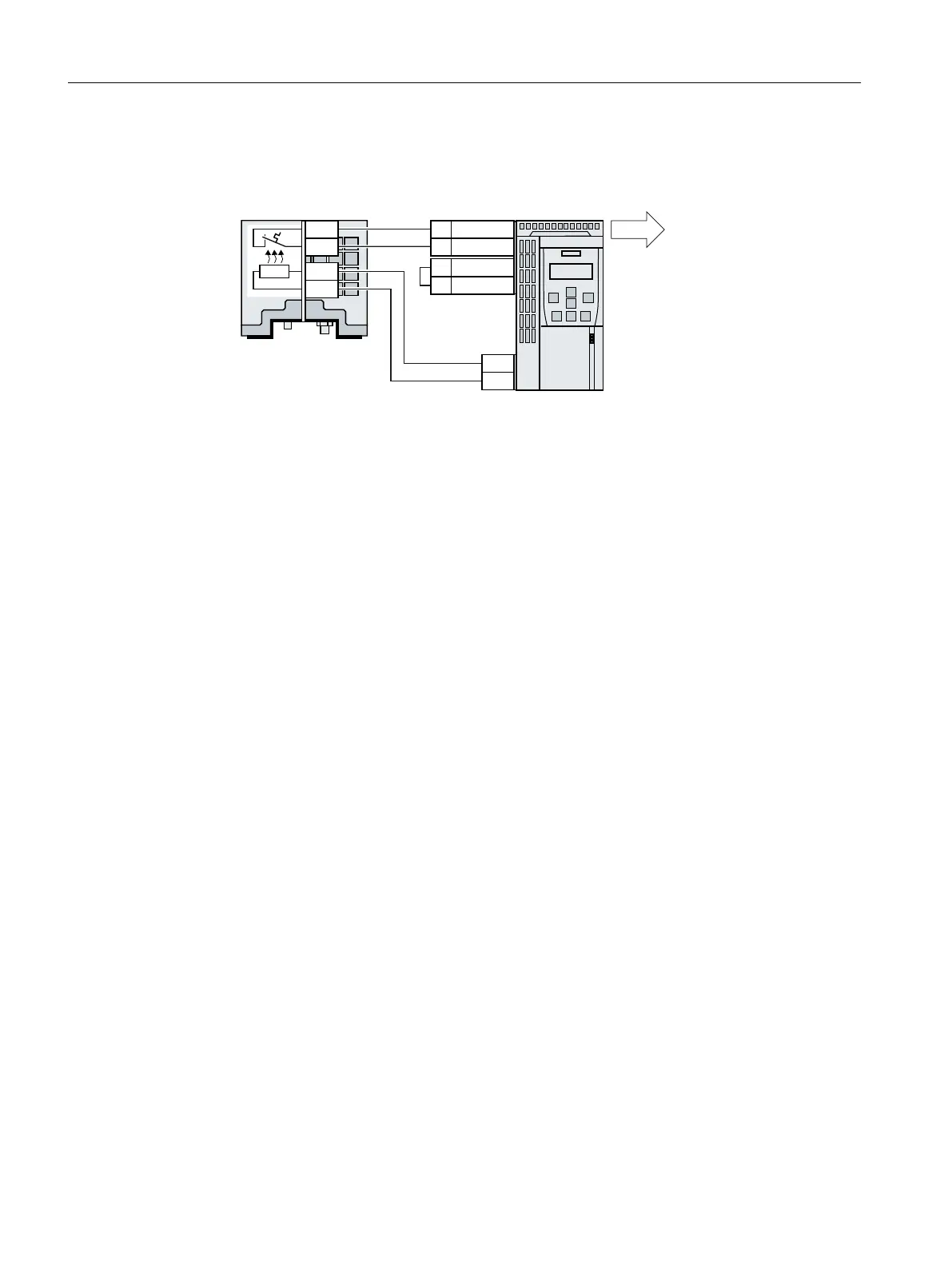
1. Connect the temperature monitoring system of the braking resistor (terminals T1 and T2 on
the braking resistor) to a free digital input on the converter.
([WHUQDOIDXOW([WHUQDOIDXOW
,QYHUWHU
%UDNLQJUHVLVWRU
5
5
5
5
7
7
9287
',
*1'
',&20
Figure4-48 Example: Temperature monitoring of the braking resistor via digital input DI3 on the
Control Unit
2. Dene the function of the digital input used as an external fault with p2106.
As an example with temperature monitoring via digital input DI3: p2106=722.3.
You have ensured that the temperature is monitored.
❒
Installing
4.12Monitoring the temperature of the braking resistor
SINAMICS G120C Converters
118 Operating Instructions, 02/2023, FW V4.7 SP14, A5E34263257B AK