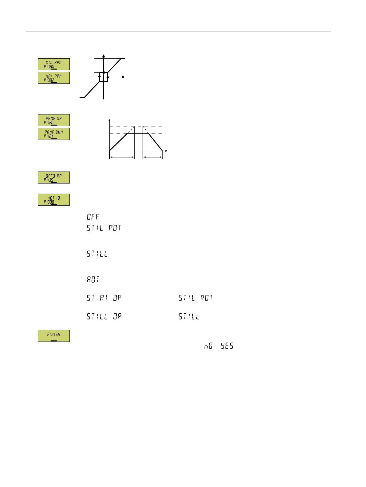
Figure5-7 Minimum and maximum motor speed
Q
6HWSRLQW
S
S
W
Q
PD[
S
Figure5-8 Ramp-up and ramp-down time of the motor
Ramp-down time after the OFF3 command
Motor data identication: Select the method which the converter uses to measure the data of
the connected motor:
• : Motor data is not measured
• : Recommended setting: Measure the motor data at standstill and with the
motor rotating.
The converter switches o the motor after the motor data identication has been completed.
• : Default setting: Measure the motor data at standstill.
The converter switches o the motor after the motor data identication has been completed.
Select this setting if the motor cannot rotate freely.
• : Measure the motor data while the motor is rotating.
The converter switches o the motor after the motor data identication has been completed.
• : Setting the same as
After the motor data identication, the motor accelerates to the current setpoint.
• : Setting the same as
After the motor data identication, the motor accelerates to the current setpoint.
Complete the data entry for quick commissioning as follows:
1. Switch over the display using an arrow key: →
2. Press the OK key.
You have entered all of the data that is necessary for the quick commissioning of the
converter.
❒
Commissioning
5.4Quick commissioning using the BOP-2 operator panel
SINAMICS G120C Converters
132 Operating Instructions, 02/2023, FW V4.7 SP14, A5E34263257B AK