0RWRUL]HGSRWHQWLRPHWHUVHWSRLQW
DIWHUWKHUDPSIXQFWLRQJHQHUDWRU
0RWRUL]HGSRWHQWLRPHWHU
VHWSRLQWORZHU
0RWRUL]HGSRWHQWLRPHWHU
VHWSRLQWKLJKHU
,QSXWV2XWSXW3DUDPHWHU
S
U
S
023
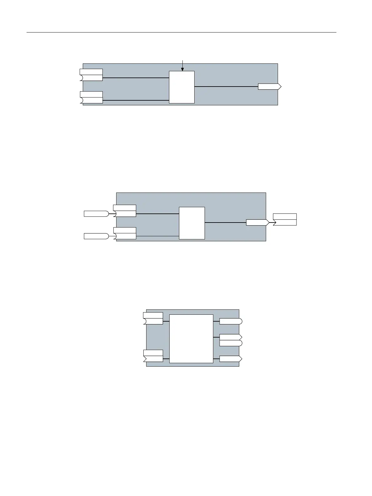
FigureA-1 Example of a block: Motorized potentiometer (MOP)
Most of the blocks can be adapted to specic applications using parameters.
You cannot change the signal interconnection within the block. However, the
interconnection between blocks can be changed by interconnecting the inputs of a block
with the appropriate outputs of another block.
The signal interconnection of the blocks is realized, contrary to electric circuitry, not using
cables, but in the software.
0DLQVHWSRLQW
0RWRUL]HGSRWHQWLRPHWHU
VHWSRLQWDIWHUWKH
UDPSIXQFWLRQJHQHUDWRU
0RWRUL]HG
SRWHQWLRPHWHU
VHWSRLQWORZHU
0RWRUL]HG
SRWHQWLRPHWHU
VHWSRLQWKLJKHU
352),GULYH
UHFHLYH3='
ELWE\ELW
S
U
U
S
U
S
023
FigureA-2 Example: Signal interconnection of two blocks for digital input 0
Binectors and connectors
Connectors and binectors are used to exchange signals between the individual blocks:
• Connectors are used to interconnect "analog" signals (e.g. MOP output speed)
• Binectors are used to interconnect digital signals (e.g. "Enable MOP up" command)
%,&2EORFN
%LQHFWRULQSXW
%LQHFWRURXWSXW
%LQHFWRUFRQQHFWRURXWSXW
&RQQHFWRURXWSXW
&RQQHFWRULQSXW
S[[[[
U[[[[
U[[[[
U[[[[
U[[[[
S[[[[
%,
&2
%2
&2%2
&,
FigureA-3 Symbols for binector and connector inputs and outputs
Binector/connector outputs (CO/BO) are parameters that combine more than one binector
output in a single word (e.g. r0052 CO/BO: status word 1). Each bit in the word represents
a digital (binary) signal. This summary reduces the number of parameters and simplies
parameter assignment.
Binector or connector outputs (CO, BO or CO/BO) can be used more than once.
Appendix
A.2Interconnecting signals in the converter
SINAMICS G120C Converters
462 Operating Instructions, 02/2023, FW V4.7 SP14, A5E34263257B AK