Removing
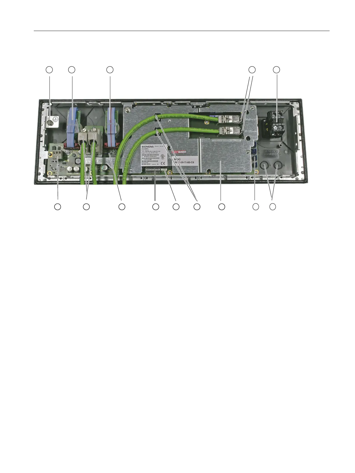
① Ground terminal
② X30 Feedrate override
③ X31 Spindle override
④ X20 Port 1: Connection: PLC I/O interface based on PROFINET
X21 Port 2: Connection: PLC I/O interface based on PROFINET
⑤ Slot for Emergency Stop
⑥ Mounting slots for additional command devices
⑦ Customer-specific inputs and outputs
⑧ Cover plate
⑨ Ethernet cable strain relief
⑩ LED
⑪ S2 Switch for setting the MCP address
⑫ S1 Switch for setting the handwheel signal type
⑬ X60 Handwheel connection
X61 Reserved
⑭ X10 Power supply interface
Figure 4-11 MCP 483C PN rear side
Procedure:
1. Switch-off the control: Completely switch off the system. Check that the system is in a no-
voltage condition and is locked-out so that it cannot be switched on again without the
appropriate authorization.
2. Access the operator panel/control cabinet in which the machine control panel is located.
3. Using a multimeter, check the X10 power supply to ensure that the system really is in a no-
voltage condition.
Service cases - hardware
4.5 Machine control panels
Software and hardware
Service Manual, 08/2018, 6FC5397-5DP40-6BA1 101

 Loading...


