Connecting
6.2 Electrical connections
62
Quick Start
Compact Operating Instructions, 05/2018, A5E31805656-06
5. Insert the signal cable through this cable gland ③.
6. Insert the stripped conductors of the signal cable into the terminal block in accordanc
e
w
ith the terminal assignment.
7. Fasten the signal cable in the cable gland
③. To do this, tighten the union nut to a torque
of 3 Nm.
8. Insert the shielding plate
② in the wall-mounted device again and fasten it with screws.
9. Close the door of the wall-mounted device and tighten the six screws
① again.
Connecting the Ethernet cable
Establishing a shield for the Ethernet cable
Note
Metalized cable gland
The metalized cable gland required for shielding is included i
n the scope of delivery.
1. Prepare the Ethernet cable:
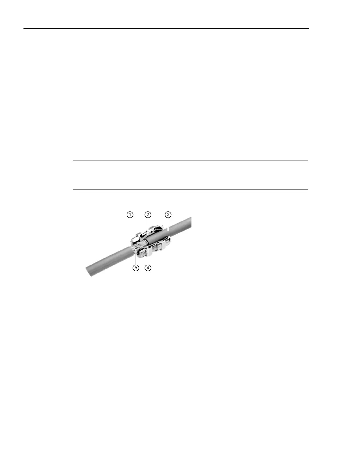
Figure 6-16 Ethernet cable shielding
– Isolate the Ethernet cable ③ at the desired location so that the braid ⑤ is exposed
over a length of approx. 1 cm.
– Insert the Ethernet cable through the cable gland. Make sure that the expos
ed
s
hielding braid rests on the shield contact
② or ④.
– Screw the cable gland closed.
 Loading...


