Connecting
6.2 Electrical connections
Quick Start
Compact Operating Instructions, 05/2018, A5E31805656-06
71
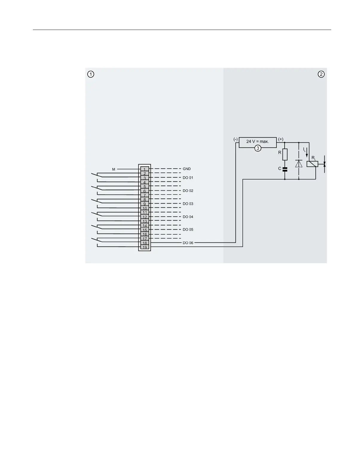
Overview: Spark suppression for wall-mounted device
Standard terminal block, terminal row A: Function in the analyzer
Terminal end/spark suppression
DO Digital outputs: Contact load max. 24 V/1.7 A, AC/DC. Shown relay contacts: relay coil has
Figure 6-24 Wall-mounted device: Example of spark suppression on a relay contact
Measures to suppress sparks
Observe the following information on spark suppression:
● To suppress sparks via relay contacts, you can use RC elements. In direct current
operation, you can also use a spark killer diode instead of the RC element.
● The RC element results in a drop-out delay for an inductive component, for example,
a
s
olenoid valve. To rate the RC element accordingly, use the following rule of thumb:
– R [ Ω ] ≈ 0.2 x R
L
[ Ω ]
– C [μF] ≈ I
L
[ A ]
● You must use a non-polarized capacitor "C".
● When connecting the RC element, refer to the previous figure/figures.
 Loading...


