Functions
6-117SJ62 Manual
C53000-G1140-C121-1
Voltage Connection Address 97&RQQHFWLRQ specifies how the voltage transformers are connect-
ed. When the voltage transformers are connected in a wye configuration, address
is set at 9DQ, 9EF, 9FQ. When the voltage transformers are connected as shown
in Figure A-12 of Appendix Section A.3, address should be set at 9DE, 9EF, 9*QG. The
latter setting is also selected when only two phase-to-phase voltage transformers are
utilized or when only the displaced voltage (zero sequence voltage) is connected to
the device.
Nominal Frequency Address 5DWHG)UHTXHQF\ corresponds to the frequency at which the protect-
ed equipment operate. The setting is dependent on the model number of the relay pur-
chased, and must be in accordance with the nominal frequency of the power system.
Units of Length Address 'LVWDQFH8QLW corresponds to the units of length (km or miles) ap-
plicable to fault locating. If a fault locator is not included with the device, or if the fault
locating function is disabled, this setting has no effect on operation of the device.
Changing the length unit will not result in an automatic conversion between the sys-
tems. Such conversions must be entered at the appropriate addresses.
6.1.1.1 Settings
In the list below, the setting ranges and default setting values for the pickup currents
are for a device with a nominal current rating I
N
= 5 A. For a nominal current rating I
N
= 1 A, divide the Setting Options values and Default Setting values by 5. Consider the
current transformer ratios when setting the device with primary values.
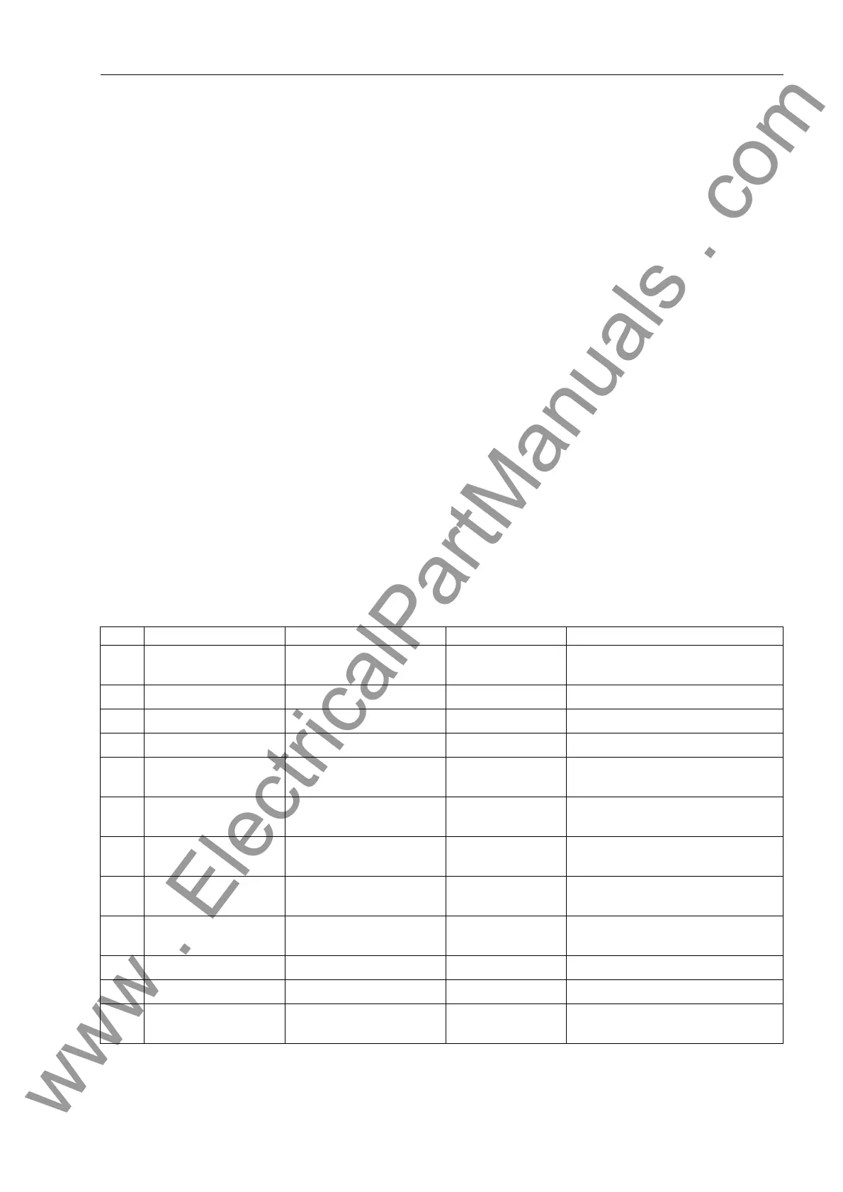
Addr. Setting Setting Options Default Setting Comment
201 CT Starpoint towards Line
towards Busbar
towards Line Location of CT starpoint
202 Vnom PRIMARY 0.10 ~ 400.00 kV 12.00 kV Primary Voltage
203 Vnom SECONDARY 100 ~ 125 V 120 V Secondary Voltage
204 CT PRIMARY 10 ~ 50000 A 100 A CT Rated Primary Current
205 CT SECONDARY 1 A
5 A
5 A
1
) CT Rated Secondary Current
206 Vph / Vdelta 1.00 ~ 3.00 1.73 Phase to open delta voltage conver-
sion factor
207 CT N / CT Ph 0.010 ~ 1.000 1.000 Neutral CT to Phase CT conversion
factor
208 CT Ns / CT Ph 0.001 ~ 1.000 1.000 Neutral I
Ns
CT to Phase CT conver-
sion factor
209 PHASE SEQ. A B C
A C B
A B C Phase sequence
210 TMin TRIP CMD 0.01 ~ 32.00 s 0.15 s Minimum Trip Command Duration
211 TMax CLOSE CMD 0.01 ~ 32.00 s 1.00 s Maximum Close Command Duration
212 Bkr Closed I MIN 0.20 ~ 5.00 A 0.20 A
1
) Closed Breaker Min. Current
Threshold
www . ElectricalPartManuals . com
 Loading...


