Functions
6-32 7SJ62 Manual
C53000-G1140-C121-1
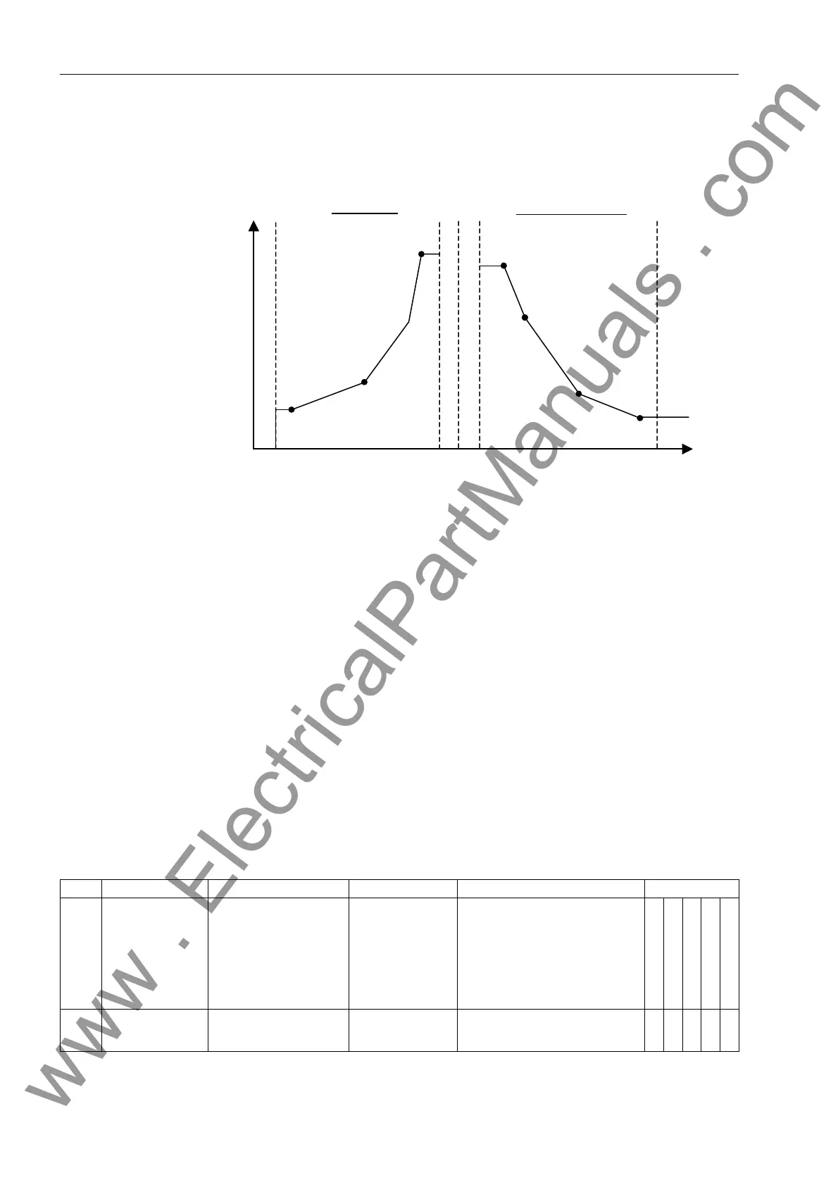
The time and current value pairs are entered at address to recreate the drop-
down curve. The following must be observed:
Figure 6-18 Use of a User-Specified Curve
− Current flows which are greater than the
largest
current value entered will not lead
to an extension of the reset time beyond the time associated with the
largest
current
value entered. The reset curve (see Figure 6-18) represents constant reset time for
currents larger than the largest current value entered.
− Current flows which are less than the
smallest
current value entered will not lead to
a reduction of the reset time below the time associated with the
smallest
current val-
ue entered. The reset curve (see Figure 6-18) represents constant reset time for
currents smaller than the smallest current value entered.
− Current flows less than 0.05 * 51 pickup setting will cause immediate reset.
6.2.2.2 Settings for Phase Overcurrent Protection
In the list below, the setting ranges and default setting values for the pickup currents
are for a device with a nominal current rating I
N
= 5 A. For a nominal current rating I
N
= 1 A, divide the Setting Options values and Default Setting values by 5. Consider the
current transformer ratios when setting the device with primary values.
0.05
0.9 1
1.1
20
t
I
Largest Current Point
Smallest Current Point
Smallest Current Point
Largest Current Point
Reset Curve
Characteristic Curve
Addr. Setting Title Setting Options Default Setting Comments Configuration
Definite Time Only
IEC Curve
ANSI Curve
User Defined Pickup
User def. Reset
1201 FCT 50/51 ON
OFF
ON Time-overcurrent protection
enabling
XXXXX
www . ElectricalPartManuals . com
 Loading...


