Functions
6-160 7SJ62 Manual
C53000-G1140-C121-1
6.17.7 Malfunction Responses of the Monitoring Functions
Depending on the type of malfunction discovered, an annunciation is sent, a restart of
the processor system is initiated, or the device is taken out of service. after three un-
successful restart attempts. The live status contact operates to indicate the device is
malfunctioning. Also, the red LED “ERROR” lights up on the front cover, if the internal
auxiliary voltage is present, and the green “RUN” LED goes out. If the internal power
supply fails, then all LEDs are dark. Table 6-6 shows a summary of the monitoring
functions and the malfunction responses of the relay.
.
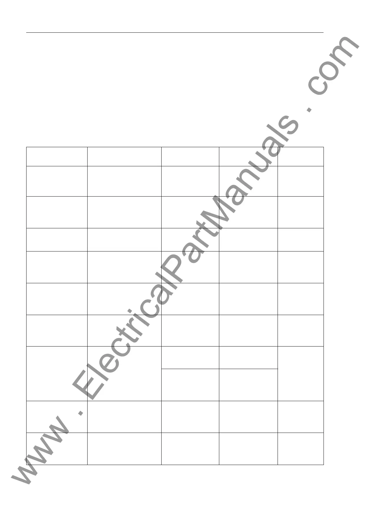
Table 6-6 Summary of the Device Malfunction Responses
Monitoring Possible Cause Malfunction Re-
sponse
Message Output
AC/DC Supply
Voltage Loss
External (aux. Voltage)
Internal (power supply)
Device shutdown All LEDs dark Live status
contact de-
energized
Internal Supply
Voltages
Internal (power supply)
Ribbon cable
disconnected
Device shutdown LED “ERROR” Live status
contact de-
energized
2
)
Battery Internal battery
discharged
Annunciation “)DLO%DWWHU\”
(FNo. 177)
Hardware Watchdog Internal (processor
failure)
Restart attempt
1
)
LED “ERROR” Live status
contact de-
energized
2
)
Software Watchdog Internal
(program sequence)
Restart attempt
1
)
LED “ERROR” Live status
contact de-
energized
2
)
ROM Internal (Hardware)
Restart attempt
1
)
LED “ERROR”
Live status
contact de-
energized
2
)
RAM Internal (Hardware) Detection during
boot sequence
LED blinks
Live status
contact de-
energized
2
)
Detection during
operation:
Restart attempt
1
)
LED “ERROR
Settings Internal (Hardware)
Restart attempt
1
)
LED “ERROR” Live status
contact de-
energized
2
)
Analogue data
acquisition
Internal (Hardware) Device shutdown LED “ERROR” Live status
contact de-
energized
2
)
www . ElectricalPartManuals . com
 Loading...


