Hardware and Connections
2-12 7SJ62 Manual
C53000-G1140-C121-1
2.1.4 Connections to Optical Communication Interfaces
Optical
Communication
Interfaces
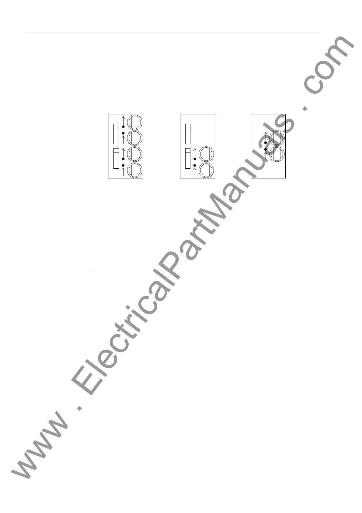
The two available versions of optical communication interfaces are shown in Figure 2-
12. The ports are supplied with caps to protect the optical components against dust or
other contaminants. The caps can be removed by turning them 90° to the left.
Figure 2-12 Optical Communication Interfaces with Protective Caps
Connections to
Optical
Communication
Interfaces
Optical Connector Type: ST–Connector
Fiber Type: Multimode graded-index (“G”) optical fiber
G50/125 µm,
G62.5/125 µm,
G100/140 µm
Wavelength: λ = 820 nm (approximately)
Allowable Bending Radius:
For indoor cable r
min
= 2 in (5 cm)
For outdoor cable r
min
= 8 in (20 cm)
Laser class 1 (acc. EN 60825–1) is achieved with fiber type G50/125 µm and
G62.5/125 µm.
2 Channel 1 Channel
Ch1
P-Slave
Ch2
P-Master
UART
Ch1
P-Slave AMO
1 Channel
www . ElectricalPartManuals . com
 Loading...


